13. SPI
13.1. Introduction
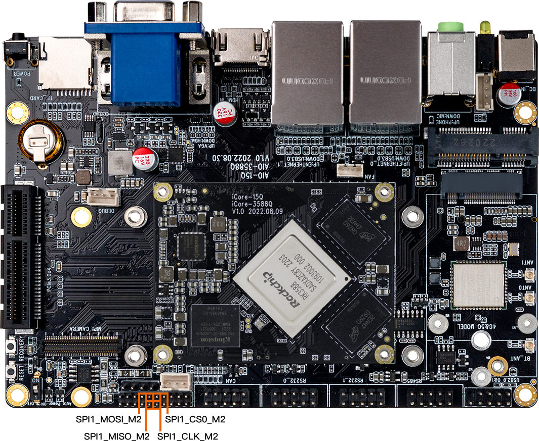
SPI is a high-speed, full-duplex, synchronous serial communication interface for connecting microcontrollers, sensors, storage devices, etc. The AIO-3588MQ development board provides the SPI1 (single chip optional) interface, and the specific position is as follows:
13.2. How SPI works
SPI works in a master-slave mode, which typically has one master device and one or more slave devices, requiring at least four wires, respectively:
CS		    slice selection signal
SCLK		clock letter
MOSI		master device data output and slave device data input
MISO		master device data input and slave device data output
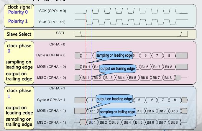
The Linux kernel uses a combination of CPOL and CPHA to represent the four working modes of the current SPI:
CPOL=0,CPHA=0		SPI_MODE_0
CPOL=0,CPHA=1		SPI_MODE_1
CPOL=1,CPHA=0		SPI_MODE_2
CPOL=1,CPHA=1		SPI_MODE_3
- CPOL : Represents the state of the initial level of the clock signal, 0 is the low level and 1 is the high level.
- CPHA : Is sampling along which clock, 0 is sampling along the first clock and 1 is sampling along the second clock.
The waveforms of SPI’s four working modes are as follows:
13.3. Drive coding
The following XM25QU128C Flash module as an example of a simple introduction to the preparation of SPI driver.
13.3.1. Hardware connection
The hardware connection between AIO-3588MQ and XM25QU128C is shown in the following table:
| XM25QU128C | AIO-3588Q |
|---|---|
| /CS | SPI1_M2_CS0 |
| D0 | SPI1_M2_RX |
| GND | GND |
| VCC | 1.8V |
| CLK | SPI1_M2_CLK |
| D1 | SPI1_M2_TX |
13.3.2. Makefile/Kconfig
Add the corresponding driver file configuration in kernel-5.10/drivers/spi/Kconfig:
config SPI_FIREFLY
       tristate "Firefly SPI demo support "
       default y
        help
          Select this option if your Firefly board needs to run SPI demo.
Add the corresponding driver file name in kernel-5.10/drivers/spi/Makefile:
obj-$(CONFIG_SPI_FIREFLY) += spi-firefly-demo.o
13.3.3. Configure the DTS nodes
Add SPI driver node description in kernel-5.10/arch/arm64/boot/dts/rockchip/rk3588-firefly-demo.dtsi, as shown below:
/* Firefly SPI demo */
&spi1{
spi_demo: spi_demo@00{
compatible = "firefly,rk3588-spi";
status = "okay";
reg = <0x00>;
spi-max-frequency = <50000000>;
//spi-cpha; /* SPI mode: CPHA=1 */
//spi-cpol; /* SPI mode: CPOL=1 */
//spi-cs-high;
};
};
&spidev1 {
status = "disabled";
};
- status : set
okayif you want to enable SPI, ordisableif not. - spi-demo@00 : since
CS0is used in this example, it is set to00; ifCS1is used, it is set to01. - compatible : the attribute here must be
compatiblewith the member of the structure in the driver:of_device_id. - reg : this is consistent with
spi-demo@00, set to:0x00in this example. - spi-max-frequency : set the highest frequency used by spi here. AIO-3588MQ supports up to 48000000.
- spi-cpha,spi-cpol : the working mode of spi is set here. The working mode of the module spi used in this example is SPI_MODE_0 or SPI_MODE_3. Here we choose SPI_MODE_0. If SPI_MODE_3 is used, open spi-cpha and spi-cpol in spi_demo.
13.3.4. Define SPI drivers
Create a new driver file in kernel-5.10/drivers/spi/, such as: spi-firefly-demo.c.
Before defining the SPI driver, the user first defines the variable of_device_id. Of_device_id is used to call the device information defined in the DTS file in the driver. The definition is as follows:
static struct of_device_id firefly_match_table[] = { {.compatible = "firefly,rk3588-spi",},{},};
The compatible values here are consistent with those in the DTS file.
Spi_driver is defined as follows:
static struct spi_driver firefly_spi_driver = {
    .driver = {
        .name = "firefly-spi",
        .owner = THIS_MODULE,
        .of_match_table = firefly_match_table,},
    .probe = firefly_spi_probe,};
};
13.3.5. Registration of SPI equipment
Static int __init firefly_spi_init(void) registers SPI driver with kernel: spi_register_driver(&firefly_spi_driver);
If the kernel is successfully matched on startup, the SPI core will configure SPI’s parameters (mode, speed, etc.) and call firefly_spi_probe.
13.3.6. Read-write SPI data
Firefly_spi_probeUSES two interface operations to read the ID ofXM25QU128C:- The
firefly_spi_read_xm25x_id_0interface directly USESspi_transferandspi_messageto transmit data. - The
firefly_spi_read_xm25x_id_1interface USES the SPI interfacespi_write_then_readto read and write data.
After success, it will print:
console:/ $  dmesg | grep spi
[    1.791786] [    T1] firefly-spi spi1.0: Firefly SPI demo program
[    1.791788] [    T1] firefly spi demo
[    1.791795] [    T1] firefly-spi spi1.0: firefly_spi_probe: setup mode 0, 8 bits/w, 50000000 Hz max
[    1.791797] [    T1] spi demo mode ; 0
[    1.791838] [    T1] firefly_spi_read_xm25x_id_0 ID = 20 41 18
[    1.791875] [    T1] firefly_spi_read_xm25x_id_1 ID = 20 41 18
13.3.7. Open SPI demo
spi-firefly-demo is not opened by default. If necessary, the demo driver can be opened with the following patch:
--- a/kernel-5.10/arch/arm64/boot/dts/rockchip/rk3588-firefly-demo.dtsi
+++ b/kernel-5.10/arch/arm64/boot/dts/rockchip/rk3588-firefly-demo.dtsi
@@ -64,7 +64,7 @@ /* Firefly SPI demo */
 &spi1 {spi_demo: spi-demo@00{
 -                status = "disabled";
 +                status = "okay";
                  compatible = "firefly,rk3588-spi";
                  reg = <0x00>;
                  spi-max-frequency = <50000000>;
13.3.8. Common SPI interface
Here are the common SPI API definitions:
void spi_message_init(struct spi_message *m);
void spi_message_add_tail(struct spi_transfer *t, struct spi_message *m);
int spi_sync(struct spi_device *spi, struct spi_message *message) ;
int spi_write(struct spi_device *spi, const void *buf, size_t len);
int spi_read(struct spi_device *spi, void *buf, size_t len);
ssize_t spi_w8r8(struct spi_device *spi, u8 cmd);
ssize_t spi_w8r16(struct spi_device *spi, u8 cmd);
ssize_t spi_w8r16be(struct spi_device *spi, u8 cmd);
int spi_write_then_read(struct spi_device *spi, const void *txbuf, unsigned n_tx, void *rxbuf, unsigned n_rx);
13.4. Interface usage
Linux provides a SPI user interface with limited functionality. If IRQ or other kernel driver interfaces are not required, consider using spidev interface to write user-level programs to control SPI devices. The corresponding path in the AIO-3588MQ development board is /dev/spidev1.0.
spidev corresponding driver code is kernel-5.10/drivers/spi/spidev.c.
The config in the kernel needs to select SPI_SPIDEV:
 │ Symbol: SPI_SPIDEV [=y]
 │ Type  : tristate
 │ Prompt: User mode SPI device driver support
 │   Location:
 │     -> Device Drivers
 │       -> SPI support (SPI [=y])
 │   Defined at drivers/spi/Kconfig:684
 │   Depends on: SPI [=y] && SPI_MASTER [=y]
DTS configuration is as follows:
&spi1{
status = "okay";
pinctrl-0 = <&spi1m2_cs0 &spi1m2_pins>;
max-freq = <50000000>;
spidev1: spidev@00{
compatible = "rockchip,spidev";
status = "okay";
reg = <0x0>;
spi-max-frequency = <50000000>;
};
};
Please refer to kernel-5.10/Documentation/spi/spidev.rst for detailed instructions.
13.5. FAQs
13.5.1. Q1: SPI data transfer exception?
A1 : Make sure the IOMUX configuration of SPI 4 pins is correct. Confirm that when TX sends data, TX pins have normal waveform, CLK frequency is correct, CS signal is pulled down, and mode matches the device.