DMA
This document describes the DMA module features and usage.
Module Overview
The K3 DMA controller supports three transfer directions:
- memory-to-memory
- memory-to-device
- device-to-memory
On the K3 platform, this module is accessed by the RCPU and uses the RT-Thread DMA framework to implement DMA transfers. It can move data for peripherals such as SPI and can also be used for efficient memory copying.
Functional Architecture
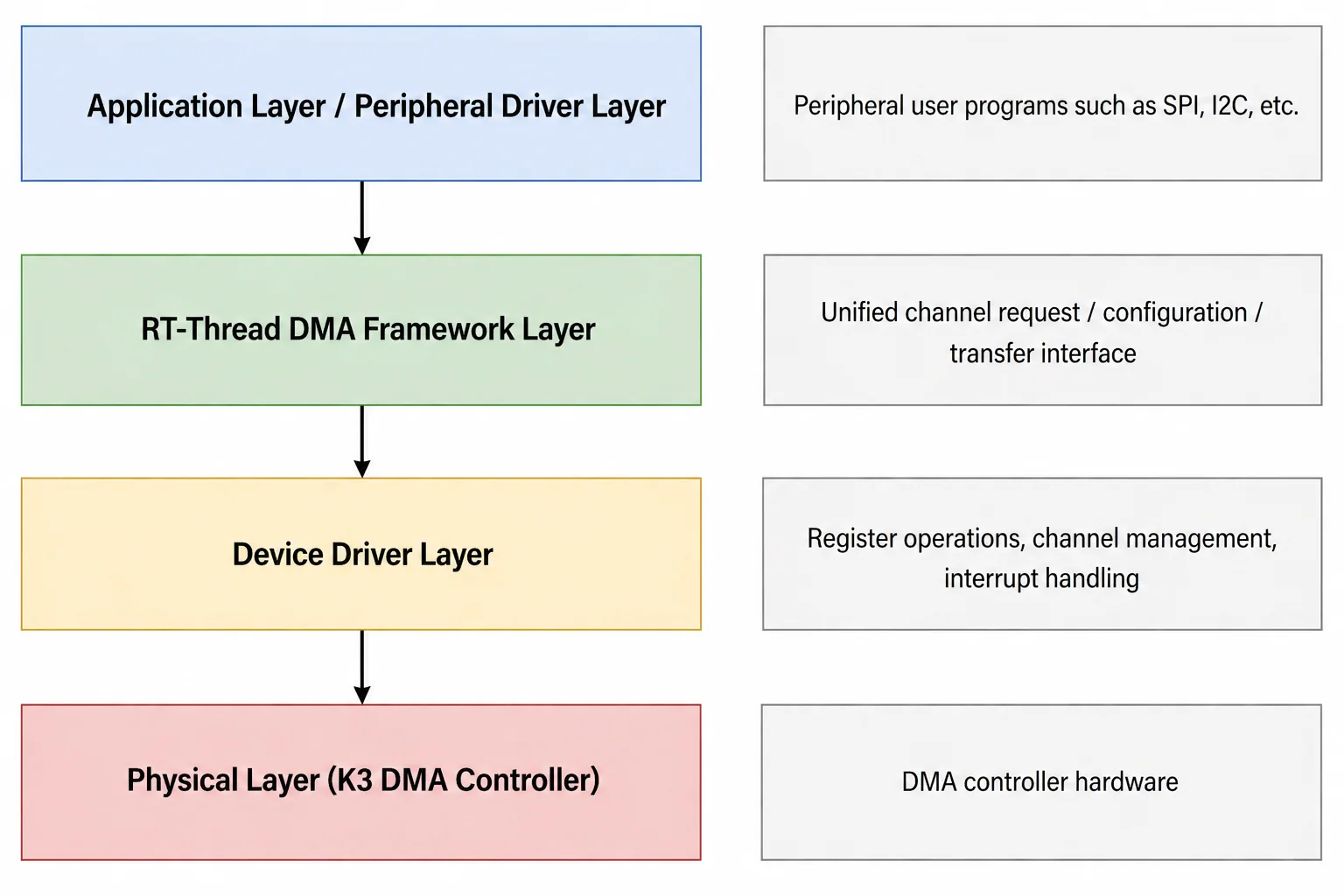
- Application layer / Peripheral driver layer: Provides DMA transfer services to applications and peripheral drivers.
- RT-Thread DMA framework layer: Provides unified interfaces for channel request, configuration, and transfer operations, while abstracting hardware differences.
- Device driver layer: Implements DMA controller register access, channel management, and interrupt handling.
- Physical layer: DMA controller hardware.
Source Code Structure
The driver source code is located in esos/bsp/spacemit/drivers/dma. The main files are listed below:
esos/bsp/spacemit/drivers/dma
.
|-- dma_k1x.c            # DMA controller core driver
|-- dma_test_k1x.c       # DMA memory-to-memory self-test tool
|-- dma_k1_spi_test.c    # SPI + DMA combined test tool
`-- SConscript
Key Features
| Feature | Description |
|---|---|
| 16-channel support | Supports up to 16 independent DMA channels running in parallel |
MEM_TO_MEM support | Memory-to-memory transfer |
MEM_TO_DEV support | Memory-to-device transfer |
DEV_TO_MEM support | Device-to-memory transfer |
| Multiple bus widths | 1 / 2 / 4 bytes (8 / 16 / 32 bits) |
| Multiple burst sizes | 8 / 16 / 32 / 64 bytes |
| Interrupt callback support | Triggers a user callback through an interrupt after the transfer completes |
| Address window remapping | On the K3 platform, the DMA address window is mapped through remap registers. The current implementation uses a fixed mapping to the 4G segment, so the upper 32 bits of the address must be 1 |
| Maximum transfer length per operation | 16 MB (24-bit counter, 0xFFFFFF bytes), also constrained by the 256 MB window boundary |
Configuration
-
BSP_USING_DMA: Enables the DMA driver.config BSP_USING_DMAbool "Enable DMA"default n -
BSP_DMA_TEST: Enables the DMA memory-to-memory self-test tool.if BSP_USING_DMAconfig BSP_DMA_TESTbool "Enable dma test driver"default nendif -
BSP_SPI_DMA_TEST: Enables the SPI + DMA combined test tool.if BSP_USING_SPI && BSP_USING_DMAconfig BSP_SPI_DMA_TESTbool "Enable spi dma test driver"default nendif
Note:
dma_k1_spi_testrequires both SPI and DMA to be available at runtime. If this option is enabled but the SPI controller is not enabled, the command cannot complete because no SPI device can be found.
DTS Properties
| Property | Description |
|---|---|
compatible | "spacemit,k1x-rdma" |
#dma-channels | Number of DMA channels, 16 by default |
max-burst-size | Maximum burst size: 8 / 16 / 32 / 64, 64 by default |
DMA Configuration for Other Modules
Peripheral drivers, such as SPI, bind DMA channels through the dmas and dma-names properties in the DTS. The handshake ID specifies the hardware handshake signal associated with the peripheral.
Handshake ID description
The handshake ID is configured by the DMA_RSSR(n) register. It selects which peripheral TX/RX request signal is connected to the DMA channel. Using SPI0 as an example, the handshake IDs are assigned as follows:
| Peripheral | TX Handshake ID | RX Handshake ID |
|---|---|---|
| SPI0 | 4 | 5 |
DTS configuration example for SPI0 with DMA
#dma-cells = <2>, and each dmas entry uses the format <&rdma handshake_id 1>:
&rspi0 {
    dmas = <&rdma 5 1
            &rdma 4 1>;
    dma-names = "rx", "tx";
};
Example Usage
Basic functional testing can be performed with the test tools on the secondary-core serial console.
DMA Memory-to-Memory Test
Command format:
dma_k1x_test [mode] [channel] [width_bytes] [burst_bytes] [count]
Parameters:
| Parameter | Description | Default |
|---|---|---|
mode | 0 = sequential test, which runs all 16 channels one by one; 1 = parallel test, which runs all 16 channels simultaneously; 2 = single-channel test | 0 |
channel | Channel number when mode=2 (0~15); ignored in other modes | 0 |
width_bytes | Bus width: 1 / 2 / 4 bytes | 4 |
burst_bytes | Burst size: 8 / 16 / 32 / 64 bytes | 32 |
count | Number of test iterations | 1 |
Examples:
-
16-channel sequential test
dma_k1x_test 0 -
16-channel parallel test
dma_k1x_test 1 -
Single-channel test using channel 3, 2-byte width, 16-byte burst, repeated 5 times
dma_k1x_test 2 3 2 16 5
SPI + DMA Combined Test
dma_k1_spi_test
This command performs the following operations in sequence:
- reads the SPI Flash JEDEC ID
- reads 256 bytes
- writes test data
- reads back the data for verification
Application Development
The DMA driver is integrated with the RT-Thread DMA framework. Peripheral drivers and applications can use standard interfaces to perform DMA transfers.
-
Request a DMA channel:
struct rt_dma_chan *chan = rt_dma_chan_request(dev, NULL); -
Configure DMA transfer parameters:
struct rt_dma_slave_config config;config.direction = RT_DMA_MEM_TO_MEM; /* or RT_DMA_MEM_TO_DEV / RT_DMA_DEV_TO_MEM */config.src_addr = src_phys_addr;config.dst_addr = dst_phys_addr;config.src_addr_width = RT_DMA_SLAVE_BUSWIDTH_4_BYTES;config.dst_addr_width = RT_DMA_SLAVE_BUSWIDTH_4_BYTES;config.src_maxburst = 32;config.dst_maxburst = 32;rt_dma_chan_config(chan, &config); -
Prepare a memory-to-memory transfer:
struct rt_dma_slave_transfer transfer;transfer.src_addr = src_phys_addr;transfer.dst_addr = dst_phys_addr;transfer.buffer_len = len;rt_dma_prep_memcpy(chan, &transfer); -
Set the callback and start the transfer:
chan->callback = my_dma_callback;rt_dma_chan_start(chan); -
Stop the transfer and release the channel:
rt_dma_chan_stop(chan);rt_dma_chan_release(chan);
FAQ
DMA Transfer Timeout
When a timeout occurs during testing, the serial console prints a log similar to the following:
[dma_k1x_test:430] seq: timeout on ch0: -1
Possible causes:
-
The DMA controller is not initialized
Check whether
BSP_USING_DMAis enabled and whether the DMA node status in the DTS is set tookay. -
The interrupt is not triggered correctly
DMA transfer completion depends on interrupt notification. Check whether the interrupt number is configured correctly and whether the interrupt handler is registered properly.
-
The address window is out of range
On the K3 platform, the DMA engine can address only a 256 MB window (
0x4000_0000~0x4FFF_FFFF). The remap registers map this window to the actual physical address. If the source or destination address exceeds the window range, the driver prints messages such as:DMA addr outside 256MB window: off_src=0x... off_dst=0x... len=0x...DMA xfer crosses window: off_src=0x... off_dst=0x... len=0x... -
The upper address bits do not meet the remap constraint
The current implementation requires the upper 32 bits of the DMA source and destination addresses to be
1, which corresponds to the 4G segment. Otherwise, the following message is printed:DMA remap only supports upper==1 (4G segment): src=0x... dst=0x...
DMA Data Verification Failure
When a test prints a log similar to the following:
[dma_k1x_test:448] seq: ch0 data mismatch.
Possible causes:
-
Cache coherency issue
Before the DMA transfer, the source buffer must be flushed from cache. After the transfer completes, the destination buffer must be invalidated from cache. Example:
rt_hw_cpu_dcache_ops(RT_HW_CACHE_FLUSH, src, len); /* before transfer */rt_hw_cpu_dcache_ops(RT_HW_CACHE_FLUSH, dst, len); /* before transfer *//* ... DMA transfer ... */rt_hw_cpu_dcache_ops(RT_HW_CACHE_INVALIDATE, dst, len); /* after transfer */ -
Burst configuration mismatch
The burst size must be one of
8,16,32, or64. Any other value causes configuration failure.
Channel Allocation Failure
If no free dma channel is printed, all 16 channels are currently in use. Release channels that are no longer needed before requesting a new one.