SPI
This document describes the SPI features and usage on the secondary core (RT-Thread).
Module Overview
SPI (Serial Peripheral Interface) is a serial communication interface between the SoC and external peripherals. Only x1 mode is currently supported. SPI supports both master and slave modes. In a typical configuration, one master controls one or more slave devices. The master provides the clock and initiates read and write operations. On the K3 secondary core, only master mode is supported.
Functional Architecture
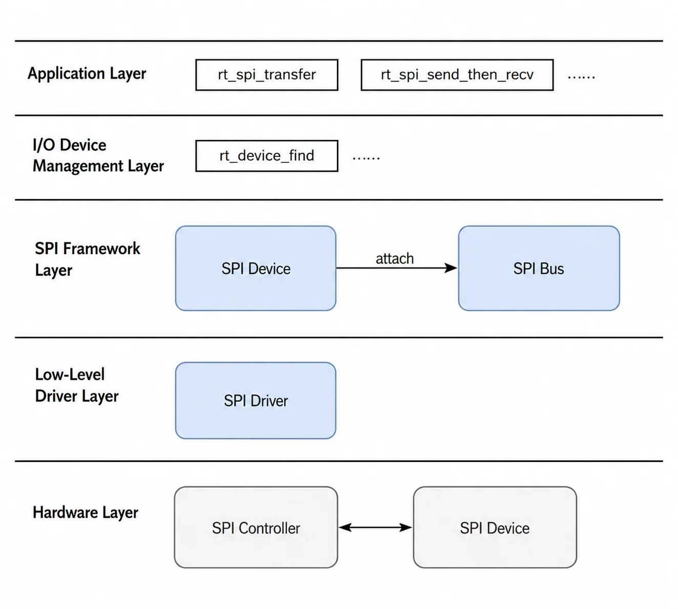
The RT-Thread SPI driver framework is part of the I/O device management framework. From top to bottom, it is divided into three layers:
- I/O device management layer and SPI framework layer:
- Provided by the RT-Thread framework.
- Includes abstractions for the SPI bus device (
struct rt_spi_bus) and SPI slave device (struct rt_spi_device). - Provides a unified application-facing API, such as
rt_spi_transferandrt_spi_send_then_recv.
- SPI controller driver (BSP driver):
- Low-level implementation for the K3 SPI hardware controller.
- Implements the hardware operation interfaces required by the SPI framework layer, such as bus configuration and low-level transmit/receive handling.
- SPI device driver:
- Driver for specific peripherals attached to the SPI bus, such as SPI NOR Flash devices and SPI sensors.
Source Code Structure
The controller driver source code is located in bsp/spacemit/drivers/spi:
|-- bsp/spacemit/drivers/spi/k1x_spi.c # K3 SPI low-level controller driver
Key Features
Features
The secondary core uses the same hardware IP as the primary core. The hardware capabilities are therefore the same:
| Feature | Description |
|---|---|
| Communication protocols | Supports SSP / SPI / MicroWire / PSP protocols |
| Communication frequency | Maximum supported frequency is 52 Mbps; minimum supported frequency is 800 Kbps |
| Data width mode | x1 |
| Supported peripherals | Supports SPI NOR Flash, SPI NAND Flash, and various SPI sensors |
Performance Parameters
-
Communication frequency
Supported frequencies are 51.2M, 25.6M, 12.8M, 6.4M, 3.2M, 1.6M, and 800k. -
Transfer width
SPI supports x1 mode only.
Test method: Use an oscilloscope or logic analyzer to measure the SCK signal frequency.
Configuration
This section covers driver enablement and DTS settings.
Kconfig Settings
-
Enable SPI framework support:
RT_USING_SPI(default:N)-> RT-Thread Components-> Device Drivers[*] Using SPI Bus/Device device drivers -
Enable SPI controller support:
BSP_USING_SPI(default:N)-> Hardware Drivers Config-> On-chip Peripheral Drivers[*] Enable SPI -
Enable DMA framework support (SPI dependency):
RT_USING_DMA(default:N)-> RT-Thread Components-> Device Drivers[*] Using Direct Memory Access (DMA) -
Enable DMA controller support (SPI dependency):
BSP_USING_DMA(default:N)-> Hardware Drivers Config-> On-chip Peripheral Drivers[*] Enable DMA
DTS Settings
pinctrl
Refer to the reference board schematic, such as the COM260 development board, to identify the pin group used by rspi and confirm the required pin configuration.
For pinctrl details, see pinctrl.
In this example, rspi0 uses the rssp0_0_cfg group defined in k3_pinctrl.dtsi.
Configuration Example
&rspi0 {
    pinctrl-names = "default";
    pinctrl-0 = <&rssp0_0_cfg>;
    clock-frequency = <26000000>; // SPI frequency setting
    k1x,ssp-disable-dma; // Disable DMA if present; DMA is enabled by default

    status = "okay";
};
Example Usage
API Description
RT-Thread provides standardized SPI interfaces for applications and peripheral drivers.
Find and get an SPI device
rt_device_t rt_device_find(const char *name);
Attach an SPI slave device to the master bus
rt_err_t rt_spi_bus_attach_device(struct rt_spi_device *device,
                                  const char           *name,
                                  const char           *bus_name,
                                  void                 *user_data);
Configure SPI device parameters
rt_err_t rt_spi_configure(struct rt_spi_device *device, struct
                          rt_spi_configuration *cfg);
Data transfer APIs
- Custom transfer, for flexible read/write operations
rt_size_t rt_spi_transfer(struct rt_spi_device *device, const void *send_buf,
                          void *recv_buf, rt_size_t length);
- Send data
rt_size_t rt_spi_send(struct rt_spi_device *device, const void *send_buf,
                      rt_size_t length);
- Send then receive - Commonly used for register reads. Chip select remains asserted throughout the operation.
rt_err_t rt_spi_send_then_recv(struct rt_spi_device *device, const void
                               *send_buf, rt_size_t send_length,
                               void *recv_buf,
                               rt_size_t recv_length);
Application Development
Refer to bsp/spacemit/drivers/spi/k1x_spi_test.c.
Debugging
MSH Command Line
RT-Thread provides the MSH command line for inspecting system device status.
Check bus and device registration:
Enter list_device in the terminal:
msh >list_device
device           type         ref count
-------- -------------------- ----------
rspi00   SPI Device           0       # Attached SPI device
rspi0    SPI Bus              0       # Registered SPI controller bus
uart0    Character Device     2
Testing
Multi-Frequency SPI Test
The spi_test command in MSH can be used to test controller read and write operations.
1. Enable the macro option: BSP_SPI_TEST
-> Hardware Drivers Config
  -> On-chip Peripheral Drivers
    -> Enable SPI (BSP_USING_SPI [=y])
      [*] Enable spi test driver
2. Use the spi_test command in MSH:
spi_test 0: Performs read/write testing at the default frequency.spi_test 1: Iterates through all supported frequencies from800kto51.2Mfor read/write testing.