14.7 I2C Bus Interface
14.7.1 Overview
The Inter-Integrated Circuit (I2C) bus is a true multi-master serial communication bus featuring collision detection and arbitration capabilities. The I2C bus interface can operate as either a master or slave device on the I2C bus. Developed by Philips Corporation, this serial interface requires only two signal lines:
- SDA: Data line for bidirectional input and output
- SCL: Clock line providing timing reference and bus control
The I2C bus enables seamless communication between the I2C unit and various external I2C peripherals or microcontrollers. Its simple hardware design provides an efficient and cost-effective method for transferring control and status information between on-chip and off-chip devices.
The I2C bus interface resides on the peripheral bus and supports:
- Data transfer via a buffered interface for reliable communication
- Control and status management through memory-mapped registers
14.7.2 Features
- Supports up to 10 independent I2C interfaces.
- Compliant with the I2C bus specification version 2.1, except for:
- Hardware general call support
- 10-bit slave addressing
- CBUS compatibility
- Supports Multi-Master operation and bus arbitration
- Supports the following operation modes and speeds:
- Standard Mode: up to 100 Kbps
- Fast Mode: up to 400 Kbps
- High-Speed Slave Mode: up to 3.4 Mbps (High-Speed I2C only)
- High-Speed Master Mode: up to 3.3 Mbps (High-Speed I2C only)
Note:
- In High-Speed Master Mode, operational frequency is limited by the value of the pull-up resistors on the bus.
- The SCL frequency f is inversely proportional to the pull-up resistor R (i.e. f ∝ 1/R).
14.7.3 Functional Description
I2C is a serial protocol used for communication between devices (agents) on the bus. It operates through a 2-pin interface as follows:
- SDA (Serial Data and Address): Carries data and address information.
- SCL (Serial Clock Line): Provides the clock signal to synchronize communication.
Each device on the I2C bus is identified by a unique 7-bit address and can function as either a transmitter or receiver in Master or Slave mode.
The key I2C terminology is tabled below.
| I2C terminology | Definition |
|---|---|
| Transmitter | Sends data over the I2C bus |
| Receiver | Receives data over the I2C bus |
| Master | Initiates transfers, generates clock signals, and terminates transactions |
| Slave | Responds to the master's requests by transmitting or receiving data |
| Multi-master | Allows multiple masters to control the bus without corrupting messages |
| Arbitration | Ensures that only one master controls the bus when multiple masters compete. This technique avoids message corruption |
| Acknowledge | A response by the receiver to the master's acknowledge clock pulse on SCL The acknowledge can be either positive (ACK) or negative (NAK) |
| ACK | Positive Acknowledge: The receiver pulls SDA low during the clock pulse |
| NAK | Negative Acknowledge: The receiver keeps SDA high during the clock pulse |
14.7.3.1 Block Diagram
The architecture of I2C bus interface is depicted below.
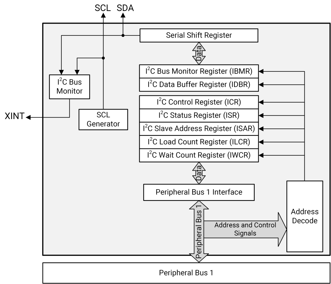
The I2C unit is a peripheral device that resides on the peripheral bus, and it interacts with the CPU through an interrupt mechanism or software polling:
- Interrupts notify the CPU about specific events on the I2C bus
- Software polling involves checking the I2C Status Register to track I2C activity without using interrupts
The I2C consists of:
-
Two-wire interface to the I2C bus
-
An 8-bit buffer for passing data
-
A set of Control and Status registers
-
A Shift register for parallel/serial conversions
-
FIFO Mode:
- TX FIFO: 8-entry buffer for outgoing data
- RX FIFO: 16-entry buffer for incoming data
- FIFO Pointers: Read/Write registers that can be cleared by software to flush the FIFOs after a critical interrupt
For the interrupt mechanism, the I2C unit can generate interrupts to notify the CPU of specific events, such as:
- Buffer full/empty.
- Stop condition detected (as a slave).
- I2C slave address detected.
- Arbitration lost.
- Bus error condition.
Note: All interrupt conditions must be explicitly cleared by software.
About the Memory-Mapped Registers:
- The I2C unit's Control, Status, and Data registers are located in the I2C memory-mapped address space
- I2C Data Buffer Register (IDBR): 8-bit register used for transmitting and receiving data via the internal Shift register
14.7.3.2 I2C Master-Slave Operation
[Example]
The I2C can act as a master on the bus to communicate with an EEPROM as the slave:
- Master Transmitter: When the I2C sends data to the EEPROM, it operates as a master transmitter, and the EEPROM functions as a slave receiver.
- Master Receiver: When the I2C reads data from the EEPROM, it operates as a master receiver, and the EEPROM functions as a slave transmitter.
Regardless of the direction (transmitter or receiver), the master is responsible for:
- Generating the clock (SCL)
- Initiating the transaction
- Terminating the transaction
14.7.3.3 I2C Bus Structure & Clock Control
The I2C bus uses an open-drain wired-AND structure, allowing multiple devices to share and control the bus. This structure supports communication about key events, including:
- Arbitration
- Wait States
- Error Conditions
During data transfers, the master drives the SCL line:
- Data is transmitted when the clock is high
- If a slave cannot keep up with the master’s clock rate, it can hold SCL low to insert wait intervals (clock stretching)
The SCL line can be altered only in two cases:
- Another master during arbitration
- A slow slave holding the clock low to delay communication
14.7.3.4 Multi-Master & Arbitration
The I2C bus supports Multi-Master operation, allowing more than one device to initiate data transfers simultaneously. When two or more masters try to control the bus, arbitration resolves the conflict:
- If two masters send the same data, both remain in control.
- A master loses arbitration if it attempts to drive SDA high while another master is driving it low.
The SCL line is a synchronized signal formed by combining the clocks generated by all active masters through the wired-AND connection.
14.7.3.5 I2C Transaction Types
I2C transactions can be initiated by the I2C as a master or received by the I2C as a slave. Both roles can involve:
- Read operations
- Write operations
- Combined Read/Write operations
14.7.3.6 I2C Bus Interface Mode
The I2C unit can accomplish a transfer in different operational modes as summarized below.
| Mode | Description |
|---|---|
| Master-Transmit | - I2C acts as a master - Used to transmit operations - I2C sends the data - I2C generates the clock - Slave device is in Slave-Receive mode |
| Master-Receive | - I2C acts as a master - Used to receive operations - I2C receives the data - I2C generates the clock - Slave device is in Slave-Transmit mode |
| Slave-Transmit | - I2C acts as a slave - Responds to a master Read operation - I2C sends the data - Master device is in Master-Receive mode |
| Slave-Receive (default) | - I2C acts as a slave - Responds to a master Write operation - I2C receives the data - Master device is in Master-Transmit mode |
Default Mode: Slave-Receive
When the I2C unit is idle, it defaults to Slave-Receive mode. This allows the I2C interface to:
- Monitor the bus for activity.
- Receive any matching slave addresses.
High-Speed Mode Entry
The I2C unit enters High-Speed mode under the following conditions:
- It detects a HS-mode master code (slave address 00001XX, where X is either 0 or 1).
- Bit [9] of the I2C Control Register is set to 0x1 (enabling HS-mode). While in HS-mode, the I2C remains in Slave-Receive mode until further action.
Slave Address Detection/Matching
When the I2C unit detects a matching 7-bit address in the I2C Slave Address Register (ISAR), it either:
- Stays in Slave-Receive mode (for Write operations).
- Switches to Slave-Transmit mode (for Read operations). The transition depends on the Read/Write (R/nW) bit:
- R/nW is clear (0): Master intends to write → I2C remains in Slave-Receive mode.
- R/nW is set (1): Master intends to read → I2C switches to Slave-Transmit mode.
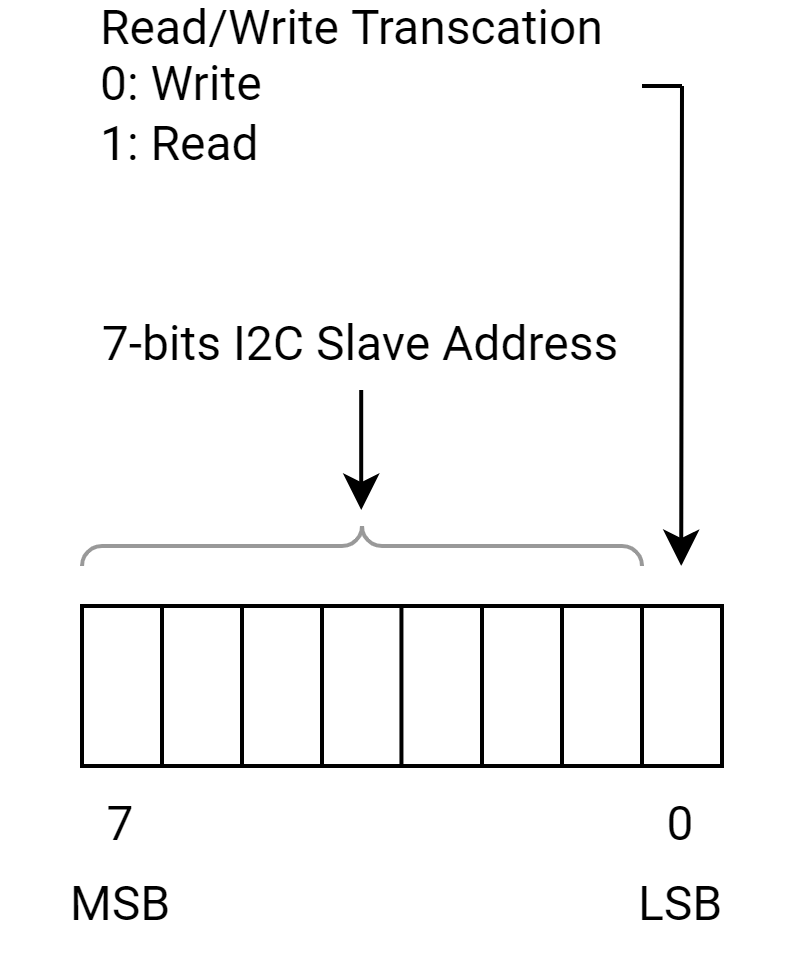
- Note: The R/nW bit is the least significant bit (LSb) in the byte containing the slave address.
Master Mode Transitions
When a peripheral initiates a transaction (Read or Write) on the I2C bus:
- The I2C unit switches from the default Slave-Receive mode to Master-Transmit mode.
- For Write Transactions:
- The I2C unit remains in Master-Transmit mode after the address transfer is completed.
- For Read Transactions:
- The I2C unit transmits the slave address and then switches to Master-Receive mode.
14.7.3.7 Start & Stop Bus States
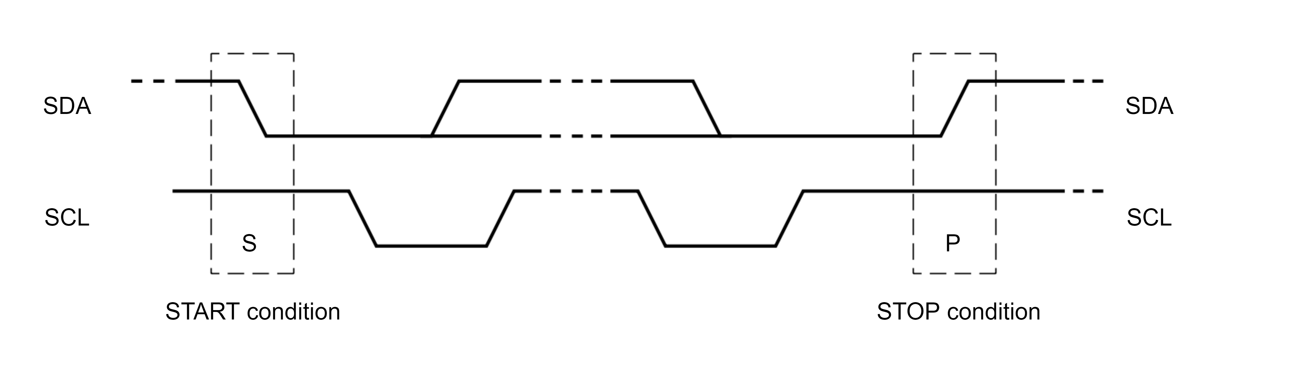
The I2C bus specification defines a Start transaction used at the beginning of a transfer and a Stop transaction used at the end of a transfer as follows:
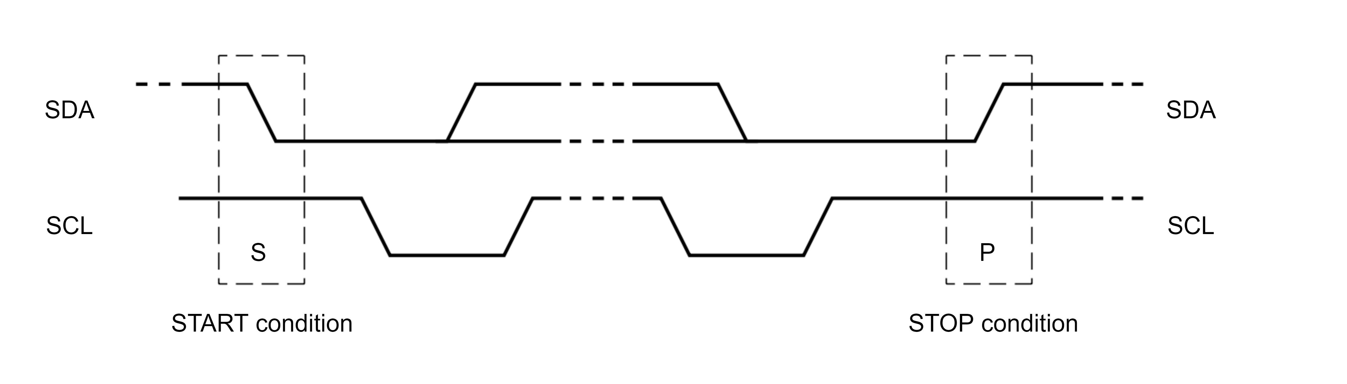
- A Start condition occurs if a high-to-low transition occurs on the SDA line when SCL is high
- A Stop condition occurs if a low-to-high transition occurs on the SDA line when SCL is high
The relationship between the SDA and SCL lines for Start and Stop is depicted below.
The I2C unit uses the ICR[START] and ICR[STOP] bits to:
- Initiate an additional byte transfer
- Initiate a Start condition on the I2C bus
- Enable data chaining (repeated Start)
- Initiate a Stop condition on the I2C bus
The definitions of the START and STOP bits in the ICR are tabled below.
| STOP Bit | START Bit | Condition | Notes |
|---|---|---|---|
| 0 | 0 | No Start or Stop | - Used for continuous data transfer without sending a Start or Stop condition. |
| 0 | 1 | Start condition and repeated Start | Starting condition: - The I2C sends a Start condition and transmits the IDBR 8-bit contents. - IDBR must contain the 7-bit slave address and the R/nW bit before a Start is initiated. For a repeated start: - The IDBR contains the target slave address and the R/nW bit. - Allows the master to perform multiple transfers to different slaves without releasing the bus. - The interface stays in Master-Transmit mode for Writes and switches to Master-Receive mode for Reads. |
| 1 | X | Stop condition | In Master-Transmit mode: - the I2C transmits the IDBR 8-bit contents and sends a Stop condition on the I2C bus. In Master-Receive mode: - ICR[ACKNAK] must be set to define a Negative-Acknowledge (NAK) pulse. - The I2C transmits the NAK pulse, places the received data byte into the IDBR, and sends a Stop condition on the I2C bus. |
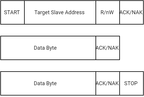
The Start and Stop Conditions of I2C are depicted below.
Start Condition
-
Control Bits:
- ICR[START] = 1
- ICR[STOP] = 0
-
Purpose:
- Initiates a master transaction or a repeated Start.
-
Procedure:
-
Software Preparation:
- Load the target slave address and the R/nW bit into the IDBR.
-
Transmission:
- Set ICR[TB] to transmit the Start condition and the IDBR contents on the I2C bus.
-
Mode Transition:
- For Write requests: The I2C bus remains in Master-Transmit mode.
- For Read requests: The I2C bus switches to Master-Receive mode.
-
Repeated Start:
- Used to change the R/nW bit or the target slave address without releasing the bus.
- The IDBR must contain the updated slave address and R/nW bit.
-
-
Arbitration Loss Handling:
- If the I2C loses arbitration while initiating a Start, it may re-attempt the Start when the bus is free.
-
Clearing:
- The Start condition is not cleared automatically by the I2C.
No Start or Stop Condition
-
Control Bits:
- ICR[START] = 0
- ICR[STOP] = 0
-
Purpose:
- Used in Master-Transmit mode for continuous data transfer (multiple bytes).
-
Procedure:
-
Data Transfer:
- Software writes a data byte to the IDBR.
- The I2C sets ISR[ITE] and clears ICR[TB].
-
Next Byte:
- Software writes the next byte to the IDBR and sets ICR[TB] to initiate the next byte transmission.
-
Continuation:
- This process repeats until software sets ICR[START] or ICR[STOP].
-
Acknowledge Pulse:
- The I2C issues an ACK/NAK as defined by ICR[ACKNAK].
-
Wait States:
- After each byte transfer (including the acknowledge pulse), the I2C holds the SCL line low to insert wait states until ICR[TB] is set.
- This allows software to prepare the next byte for transmission.
-
-
Clearing:
- ICR[START] and ICR[STOP] are not cleared automatically after transmission.
Stop Condition
The Stop condition (ICR[START]=X, ICR[STOP]=1) terminates a data transfer. In Master-Transmit mode, ICR[STOP] and ICR[TB] must be set to initiate the last byte transfer. In Master-Receive mode, the I2C must set ICR[ACKNAK], ICR[STOP], and ICR[TB] to initiate the last transfer. Software must clear ICR[STOP] after the Stop condition is transmitted.
-
Control Bits:
- ICR[START] = X (don't care)
- ICR[STOP] = 1
-
Purpose:
- Terminates a data transfer.
-
Procedure:
-
Master-Transmit Mode:
- Set ICR[STOP] and ICR[TB] to initiate the last byte transfer.
- The I2C transmits the IDBR contents and sends a Stop condition.
-
Master-Receive Mode:
- Set ICR[ACKNAK] to define a Negative-Acknowledge (NAK) pulse.
- Set ICR[STOP] and ICR[TB] to initiate the last transfer.
-
-
Clearing:
- Software must clear ICR[STOP] after the Stop condition is transmitted.
14.7.3.8 Data Transfer Sequence
The I2C unit transfers data in 1-byte increments and always follows this sequence:
- Start
- 7-bit slave address
- R/nW bit
- Acknowledge pulse
- 8 bits of data
- Acknowledge pulse
- Repeat of steps 5 and 6 for the required number of bytes
- Repeated Start (repeat step 1) or Stop
14.7.3.9 Data & Addressing Management
The I2C Data Buffer register (IDBR) and the I2C Slave Address register (ISAR) are used for managing data transfer and slave addressing. Each register plays a specific role in handling I2C communication:
- IDBR: Stores 1 byte of data or a 7-bit slave address plus the Read/Not Write (R/nW) bit
- ISAR: Holds the programmable slave address for the I2C device
Data Handling Overview
- Receiving Data: The I2C controller places incoming data into the IDBR after receiving and acknowledging a full byte
- Transmitting Data: The CPU writes data to the IDBR, and the I2C controller sends it to the serial bus when ICR[TB] is set
Master or Slave Transmit Mode
-
Data Transmission:
-
Software Writes Data:
- Software writes data to the IDBR over the internal bus
- This initiates a master transaction or sends the next data byte after ISR[ITE] is set
-
I2C Transmits Data:
- The I2C transmits data from the IDBR when ICR[TB] is set
-
Interrupts:
- If ICR[ITEIE] is set, an IDBR transmit-empty interrupt is signaled when a byte is transferred and the acknowledge cycle is complete
-
Wait States:
- If the I2C is ready to transfer the next byte but the CPU has not written to the IDBR, the I2C inserts wait states until the CPU writes a new value to the IDBR and sets ICR[TB]
-
FIFO Mode
In FIFO mode, software writes control + data information to the TX FIFO instead of the IDBR.
Master or Slave Receive Mode
-
Data Reception:
-
Software Reads Data: Software reads data from the IDBR over the internal bus after the IDBR receive-full interrupt is signaled (if ICR[DRFIE] is set)
-
I2C Transfers Data: The I2C transfers data from the Shift register to the IDBR after the acknowledge cycle completes
-
Wait States: The I2C inserts wait states until the IDBR is read by the CPU
-
Next Byte Transfer: After the CPU reads the IDBR, the I2C unit updates the ICR[ACKNAK] and ICR[TB] bits, allowing the next byte transfer to proceed
-
-
FIFO Mode:
- In FIFO mode, software reads from the RX FIFO instead of the IDBR
Addressing a Slave Device
Addressing a slave device is an important step in I2C communication.
A detailed explanation of how the I2C master addresses a slave device, different transaction types and the behavior of the I2C unit in different modes is provided in the following subsections.
Master Device Addressing a Slave
- First Byte of Transaction (as depicted below):
- The master composes and sends the first byte of the transaction
- This byte consists of:
- 7-bit slave address: Identifies the target slave device
- R/nW bit: Defines the transaction type (Read or Write)
- The first byte can also be a master code indicating the start of a high-speed transaction
- Procedure:
- Write to IDBR: The master writes the slave address and R/nW bit to the IDBR
- Transmit First Byte: The I2C transmits the first byte on the bus
- Acknowledge (ACK): The addressed slave responds with a positive-acknowledge (ACK) pulse
Transaction Types
-
When the transaction is a Write (R/nW = 0)
- The I2C remains in Master-Transmit mode
- The slave remains in Slave-Receive mode
- The master sends data to the slave
-
When the transaction is a Read (R/nW = 1)
- The I2C switches to Master-Receive mode after the ACK
- The slave switches to Slave-Transmit mode
- The master reads data from the slave
-
If the slave responds with a NAK, the I2C:
- Aborts the transaction
- Automatically sends a Stop condition
- Sets the ISR[BED] (Bus Error Detected) bit
Slave Device Behavior
-
Idle State:
- When the I2C is enabled and idle, it remains in Slave-Receive mode
- It monitors the I2C bus for a Start condition
-
Start Condition Detection:
- When a Start condition is detected, the I2C:
- Reads the first 7 bits (slave address) and compares them to the value in the I2C Slave Address Register (ISAR)
- Reads the 8th bit (R/nW bit)
- Transmits an ACK pulse if the address matches
- When a Start condition is detected, the I2C:
-
Mode Transition:
- If the address matches:
- R/nW = 0: The I2C remains in Slave-Receive mode
- R/nW = 1: The I2C switches to Slave-Transmit mode
- If the address matches:
14.7.3.10 I2C Acknowledge
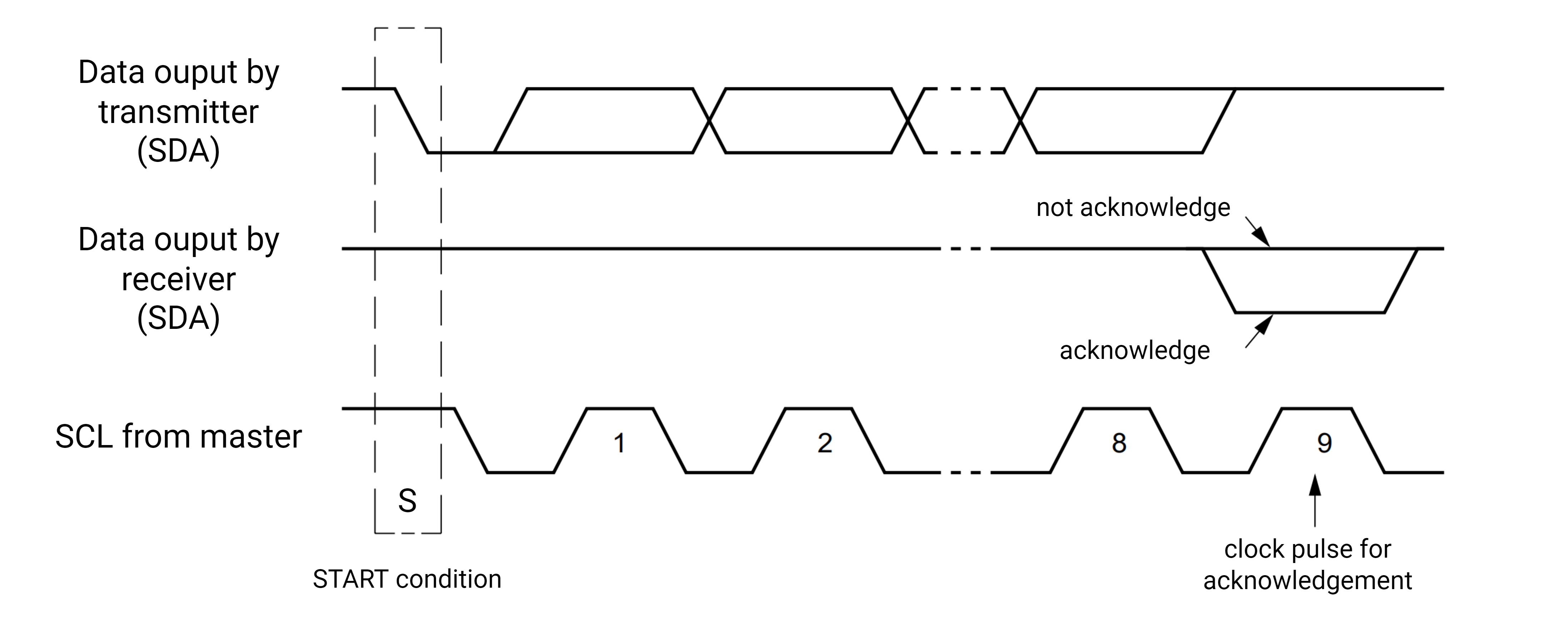
Every I2C byte transfer must be accompanied by an acknowledge (ACK) pulse that the receiver (master or slave) generates. The transmitter must release the SDA line for the receiver to transmit the acknowledge pulse. The acknowledge pulse on the I2C bus is depicted below.
Master-Transmit Mode
-
If the target slave receiver cannot generate the Acknowledge (ACK) pulse, the SDA line remains high, which indicates a Not-Acknowledge (NAK)
-
The lack of ACK causes
- The I2C sets ISR[BED]
- The associated interrupt is generated (if enabled)
- The I2C automatically generates a Stop condition and aborts the transaction
Master-Receive Mode
- The I2C sends a negative-acknowledge (NAK) pulse to signal the slave transmitter to stop sending data
- The ICR[ACKNAK] bit controls the ACK/NAK pulse value driven onto the I2C bus
Procedure:
- The master receives a byte from the slave
- The I2C automatically transmits the ACK pulse after receiving each byte from the serial bus, unless it is the last bytes
- Before receiving the last byte, software must set ICR[ACKNAK] to generate a NAK
- The NAK pulse is sent after the last byte has been sent, to signals the end of data reception (and to stop sending data)
Note: As required by the I2C bus protocol, ISR[BED] is not set for a Master-Receive mode NAK
Slave mode
-
The I2C automatically acknowledges its own slave address, regardless of the ICR[ACKNAK] setting
-
In Slave-Receive mode,
- After receiving a data byte, the slave sends an ACK automatically, regardless of the ICR[ACKNAK] setting
- The I2C unit sends the ACK pulse after receiving the 8th data bit of the byte
-
In Slave-Transmit mode,
- If the master sends a NAK, it indicates the last byte is transferred
- After sending a NAK, the master may issue either a Stop or repeated Start
- The ISR[UB] remains set until a Stop or repeated Start is detected
14.7.3.11 Arbitration
I2C bus arbitration is required due to the Multi-Master capabilities of the I2C bus. Arbitration is used when 2 or more masters simultaneously generate a Start condition within the minimum I2C hold time of the Start condition.
Arbitration Process
- Arbitration can continue for an extended period if the address field and R/nW bit are the same.
- If the address, R/nW bit, or data differ, the master whose data does not match the SDA line (i.e., the master is driving a high state while SDA is low) loses arbitration.
Wired-AND Nature of I2C
- The I2C bus uses a wired-AND configuration, meaning:
- If multiple masters output the same data, no data is lost.
- If a master outputs a high state while the bus is low, it loses arbitration.
Behavior on Arbitration Loss
When a master loses arbitration:
- The I2C unit disables the SDA and SCL drivers for the remainder of the byte transfer.
- The arbitration loss detected bit ISR[ALD] is set.
- The I2C returns to idle (Slave-Receive) mode.
Handling Arbitration Loss in FIFO mode
Software must flush the FIFOs after arbitration loss. That can be done by clearing the Read and Write pointer registers for both the Transmit and Receive FIFOs.
- WFIFO_RPTR
- WFIFO_WPTR
- RFIFO_RPTR
- RFIFO_WPTR
SCL (Serial Clock Line) Arbitration
Each master on the I2C bus generates its own clock on the SCL line for data transfers. This means that different masters may have different clock frequencies.
Since data is valid during the high period of the clock, a defined clock synchronization procedure is necessary to ensure proper communication. This is achieved through bit-by-bit arbitration.
Clock Synchronization Mechanism (as depicted below):
- Clock synchronization is achieved through the wired-AND connection of the I2C devices to the SCL line.
- High to Low Transition: When a master's clock transitions from high to low, it holds the SCL line for its own clock period.
- Low to High Transition: A clock cannot switch from low to high until all masters complete their low periods.
- The master with the longest low period holds the SCL line low. Masters with shorter low periods enter a high wait-state until the master with the longest low period completes.
- Once the master with the longest low period completes, the SCL line transitions to high, and other masters with shorter periods can continue their data cycles. The master with the longest clock period controls the SCL line, ensuring synchronized data transfer.

SDA Arbitration
Arbitration on the SDA (Serial Data Line) can extend over a significant duration, as it begins with the transmission of the address and R/nW bits and continues through the data bits. Below is depicted the arbitration procedure for two masters, although more than two masters may participate if connected to the bus.
Address & R/nW Checking
-
Condition 1: If the address and R/nW bit transmitted by multiple masters are identical, arbitration proceeds to the data bits.
- Due to the wired-AND nature of the I2C bus, no data is lost if multiple masters signal the same bus states.
-
Condition 2: If the address, R/nW bit, or data differ, the master that transmits the first high data bit loses arbitration.
- If the I2C loses arbitration:
- Stop sending by shutting off its SDA and SCL drivers for the remainder of the byte transfer.
- Sets the ISR[ALD] (Arbitration Loss Detected) bit.
- Returns to Slave-Receive mode.
- If the I2C loses arbitration:
Arbitration Loss Case 1: Re-send
- If arbitration is lost during the transfer of address bits and the I2C unit is not addressed, it re-sends the address when the bus becomes free.
- This is possible because the IDBR (I2C Data Buffer Register) and ICR (I2C Control Register) are not overwritten during arbitration loss.
Arbitration Loss Case 2: Addressed as a Slave
If the I2C loses arbitration because another bus master addresses the I2C unit as a slave device, the I2C
- Switches to Slave-Receive mode
- Overwrites the original data in register IDBR.
Software must clear the Start and re-initiate the master transaction.
Note: Software must ensure that the I2C unit does not write to its own slave address, as this causes the I2C bus to enter an indeterminate state.
Boundary conditions
Boundary conditions exist for arbitration when an arbitration process is in progress and a repeated Start or Stop condition is transmitted on the I2C bus.
To prevent errors, the I2C unit, acting as a master, no arbitration occurs in these cases:
- Between a repeated Start condition and a data bit
- Between a data bit and a Stop condition
- Between a repeated Start condition and a Stop condition
These situations arise only when different masters write the same data to the same target slave simultaneously and arbitration is not resolved after the first data-byte transfer.
Note: The software must ensure that arbitration is resolved promptly. For example:
- The software can ensure that masters send unique data by requiring each master to transmit its I2C address as the first data byte of any transaction.
- When arbitration is resolved, the winning master sends a restart and begins a valid data transfer.
- The slave discards the master's address and processes the remaining data.
14.7.3.12 High Speed Mode
Introduction
The I2C unit supports HS-mode operation with
- The slave data transfer rates up to 3.4 Mbps
- The master data transfer rates up to 3.3 Mbps
HS-mode devices maintain backward compatibility with Fast and Standard mode (F/S-mode) devices.
When operating in HS-mode, the bus protocol and data format remain the same as in F/S-mode, except for the following:
- No Clock synchronization and arbitration are performed in HS-mode. These processes are completed before HS-mode is entered.
HS-mode is entered when a master running in F/S-mode sends a master code and wins arbitration. At this point,
- The master switches to HS-mode and generates I2C transactions.
HS-mode ends when a Stop condition is generated by the master.
The master codes are a set of reserved slave addresses that are used to indicate the start of a HS-mode transfer. The master codes always win arbitration against other slave addresses. In the case of a multi-master, HS-mode system,
- Each master is assigned a unique master code. This ensures that the clock synchronization and bus arbitration finishes in F/S-mode.
- There are 8 possible master codes of the form: 8’b0000_1xxx (where x is either 0 or 1). Thus, a maximum of 8 masters are allowed in a multi-master HS-mode system.
Data Transfer in HS-mode
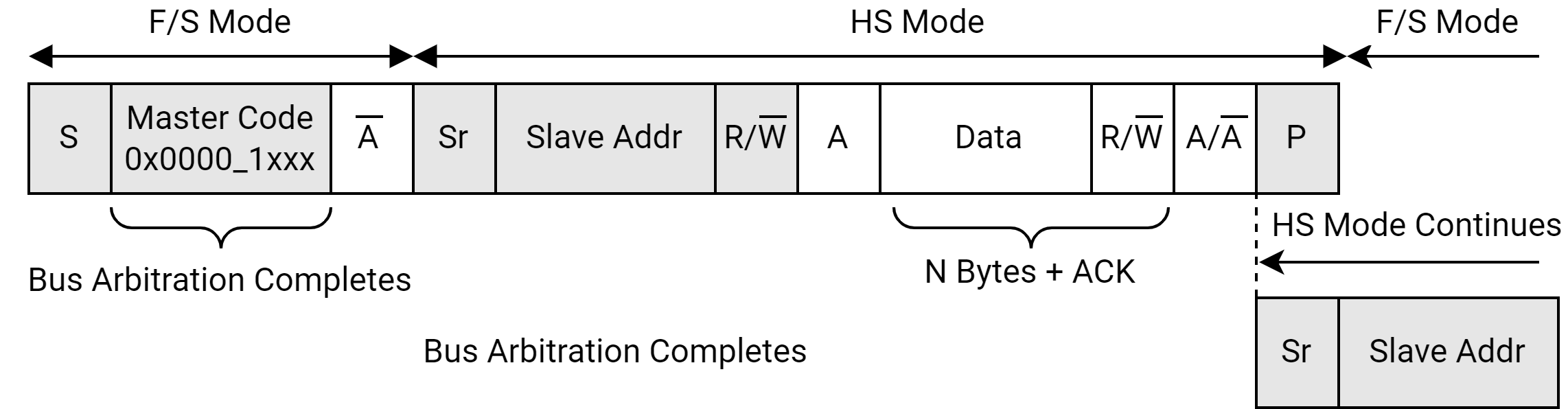
HS-mode is entered when a master running in F/S-mode sends and detects the following:
- send Start condition
- send Master Code (0x0000_1xxx)
- Detect not-acknowledge bit (A)
During this sequence, clock sync and arbitration have completed in Fast-mode and only one winning master remains. The master then switches to HS-mode and begins a bus transaction by issuing a repeated Start condition. Additional high speed data transfers can be linked by separating them with repeated start conditions. HS-mode ends when a Stop condition is sent. This sequence is depicted below.
To use the I2C unit in HS-mode as either a master or a slave, set the ICR[MODE] bits as follows:
- When MODE = 2'b10, all non-high speed transmits occur in Standard-mode.
- When MODE = 0b11, all non-high speed transmits occur in Fast-mode.
HS-mode Data Rate
According to I2C Bus Specification, the maximum data rate supported in HS-mode is dependent on the capacitive load of each bus line.
Capacitive Load:
- <100 pF: Max data rate speed (3.4 Mbps slave / 3.3 Mbps master).
- 400 pF: Data rate speed halves (1.7 Mbps slave / 1.65 Mbps master).
Note: For capacitive loads between 100 pF and 400 pF, the maximum data rate is linearly interpolated. Capacitive loads must not exceed 400 pF.
14.7.3.13 Master Operations
When software initiates a Read or Write on the I2C bus, the I2C unit switches from the default Slave-Receive mode to Master-Transmit mode. The 7-bit slave address and the R/nW bit follow the Start pulse.
After the master receives an ACK, the I2C enters 1 of 2 Master modes:
- Master-transmit - I2C writes data
- Master-receive - I2C reads data
When transmitting the master code, the master should receive a NAK and then enter HS-mode. The 7-bit slave address and the R/nW bit follow a repeated Start condition. The master receives an ACK and the I2C unit enters 1 of 2 Master modes listed above.
The CPU writes to the ICR register to initiate a master transaction. Data is read and written from the I2C unit through the memory-mapped registers. The I2C unit responsibilities as a master device are tabled below.
| I2C Master Action | Mode of Operation | Definition |
|---|---|---|
| Generate clock output | Master-transmit Master-receive | - The master drives the SCL line. - ICR[SCLE] and ICR[IUE] must be set. |
| Write target slave address to IDBR | Master-transmit Master-receive | - The CPU writes to IDBR bits [7:1] before enabling a Start condition. - The first 7 bits are sent on the I2C bus after the Start. See Section Start and Stop Bus States in this chapter. |
| Write R/nW bit to IDBR | Master-transmit Master-receive | - CPU writes to least significant IDBR bit with R/nW control bit - If the R/nW bit is low, the master remains a Master-Transmitter. If high, the master switches to a master receiver. See Section Data and Addressing Management in this chapter. |
| Signal Start condition | Master-transmit Master-receive | See Generate clock output action in this table. After the target slave address and R/nW bit are in the IDBR, - Software sets ICR[START]. - Software sets ICR[TB] to initiate the Start condition. See Section Start and Stop Bus States in this chapter |
| Initiate first data byte transfer | Master-transmit Master-receive | - The CPU writes a data byte to the IDBR - The I2C transmits the byte when ICR[TB] is set. - The I2C clears ICR[TB] and sets ISR[ITE] when the transfer is complete. |
| Arbitrate for I2C bus | Master-transmit Master-receive | If 2 or more masters signal a Start within the same clock period, arbitration must occur. - The I2C arbitrates for as long as needed. Arbitration takes place during slave address and R/nW bit or data transmission and continues until all but one master loses the bus. No data is lost. - If the I2C loses arbitration, it sets ISR[ALD] after the byte transfer is completed and switches to Slave-Receive mode. - If the I2C loses arbitration as it attempts to send the target address byte, it attempts to resend the byte when the bus becomes free. Software must ensure that the boundary conditions described in Section Boundary conditions, Operation do not occur. |
| Write one data byte to the IDBR | Master-transmit only | - Occurs when ISR[ITE] is set and ICR[TB] is clear. If the IDBR transmit-empty interrupt is enabled, the interrupt is generated. - The CPU writes 1 data byte to the IDBR, sets the appropriate START/STOP bit combination, and sets ICR[TB] to send the data. Eight bits are taken from the Shift register and written to the serial bus. The eight bits are followed by a Stop, if requested by ICR[STOP] being set. |
| Wait for Acknowledge from slave receiver | Master-transmit only | As a master transmitter, the I2C generates the clock for the acknowledge pulse. The I2C releases the SDA line to allow Slave-Receiver acknowledge transmission. See Section I2C Acknowledge. |
| Read one byte of I2C data from the IDBR | Master-receive only | Eight bits are read from the serial bus, collected in the Shift register, then transferred to the IDBR after the ICR[ACKNAK] bit is read. - The CPU reads the IDBR when ISR[IRF] is set and ICR[TB] is clear. If the IDBR receive-full interrupt is enabled, it is signalled to the CPU. - When the IDBR is read, if ISR[ACKNAK] is clear (indicating ACK), the software must clear the ICR[ACKNAK] bit and set ICR[TB] to initiate the next byte Read. - If ISR[ACKNAK] is set (indicating NAK), ICR[TB] is clear, ICR[STOP] is set, and ISR[UB] is set, then the last data byte has been read into the IDBR, and the I2C is sending the Stop. - If ISR[ACKNAK] is set (indicating NAK) and ICR[TB] is clear, but ICR[STOP] is clear, then the software has 2 options: (1) Set ICR[START], write a new target address to the IDBR, and set ICR[TB], which sends a repeated Start. (2) Set ICR[MA] and leave ICR[TB] clear, which sends a Stop only. |
| Transmit acknowledge to slave transmitter | Master-receive only | - As a master receiver, the I2C generates the clock for the acknowledge pulse and drives the SDA line during the acknowledge cycle. - If the next data byte is to be the last transaction, the user software sets ICR[ACKNAK] for NAK generation. See Section I2C Acknowledge. |
| Generate a repeated Start to chain I2C transactions | Master-transmit Master-receive | Data chaining takes place by using a repeated Start condition instead of a Stop condition. - The repeated Start is generated after the last data byte of a transaction has been transmitted on the I2C bus, as described in Section Data Transfer Sequence. - The software must write the next target slave address and the R/nW bit to the IDBR, sets ICR[START], and sets ICR[TB]. See Section Start and Stop Bus States in this chapter |
| Generate a Stop | Master-transmit Master-receive | - A Stop is generated after the last data byte of a transaction has been transmitted on the I2C bus, as described in Section Data Transfer Sequence. - ICR[STOP] must be set in order to generate the Stop condition. See Section Start and Stop Bus States in this chapter. |
14.7.3.14 FIFO mode
FIFO mode is an extension to the I2C module. The main features of FIFO mode are:
- FIFOs are added on both transmit and receive sides.
This helps reducing the number of IDBR empty/full interrupts. Instead of the core writing or reading to/from the IDBR 1 byte at a time, the FIFOs allow reading and writing multiple bytes without interrupting the core after each Byte.
- DMA mode is added.
DMA mode allows improvement in long I2C transactions (typically more than 8 bytes) where complete transaction can be programmed in DMA and allows reducing number of FIFO interrupts.
Note: FIFO mode is completely backward compatible. It is allowed to disable FIFO mode and work in I2C legacy mode by writing ICR[FIFO_EN] = 0.
Transmit FIFO (Tx FIFO)
-
Structure:
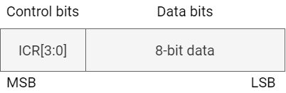
- Width: 12 bits (4-bit control word + 8-bit data)
- Number of entries: 8
- Each entry consists of a data byte concatenated with a 4-bit control word
-
Control Word:
- The control word corresponds to the ICR[3:0] bits, which required for each transmitted data byte.
-
Data Transmission Process:
- After a byte is transferred, the next byte is copied from the Tx FIFO into the shift register.
- Simultaneously, the associated control word is copied into the ICR register.
- This process continues until the STOP bit is set, signaling the end of transmission.
Receive FIFO (Rx FIFO)
-
Structure:
- Width: 8 bits (only data)
- Number of entries: 16
- Each entry stores one received byte
-
Data Handling Process:
- When the Rx FIFO is half full, it triggers either an interrupt or a DMA request.
- At this point, the stored data must be read from the FIFO.
- Any additional incoming data is stored in the remaining free entries until the FIFO is full.
FIFO Mode Support
In order to support the FIFO mode and fully utilize its capabilities, the following status and control bits were added:
- ICR[FIFO_EN]: enables FIFO mode.
- ICR[TXBEGIN]: starts a transaction.
- New status bits in ISR have been added for FIFO mode interrupts and also a bit to flag Transaction done. ICR has the enable bits for all these interrupts.
- TXDONE interrupt generated at the end of each transaction (when STOP bit is send).
- ICR[DMA_EN]: Enables or disables DMA mode and switches between DMA and PIO mode
In DMA mode, all the FIFO related interrupts have to be disabled in ICR and ICR[DMA_EN] bit has to be set. And only DMA requests are sent to the DMA and not any interrupts to the core.
Similarly in PIO mode, interrupts have to enabled and ICR[DMA_EN] bit cleared. So only interrupts to the core are generated when the Transmit FIFO is full or when the Receive FIFO is half full, full or overrun. ICR[TXDONE_IE] is for enabling Transaction Done Interrupt and needs to be set in both PIO and DMA modes. The core needs to get an interrupt after each transaction is done.
Note: This FIFO mode should only be used when the I2C is in Master mode. This FIFO mode is not for Slave mode.
14.7.3.15 I2C Serial Clock Programming Guidelines
Before each of the I2C modules has been initialized, set the clock:
- Open and select the I2C clock by setting the Clock/Reset Control Register for I2C.
- Set the I2C Load Count Register (ILCR) to the desired frequency.
14.7.3.16 Master Mode Programming Examples
Initialize Unit
- Set the slave address in the ISAR
- Enable the preferred interrupts in the ICR. Do not enable the arbitration-loss-detected interrupt
- Set ICR[MODE] to the desired bus rate. For HS-mode bus rate, the master-code must be transmitted before HS-mode bus timing is enabled. Software should always set the HS mode bit (ICR[16]) as that bit makes the I2C HS capable. This bit does not affect the non-HS transfers
- Set the ICR[IUE] and ICR[SCLE] bits to enable the I2C and SCL
Write 1 Byte as a Master
- Load target slave address and R/nW bit in the IDBR. R/nW must be 0 for a Write
- Initiate the Write
- Set ICR[START], clear ICR[STOP], clear ICR[ALDIE], set ICR[TB]
- When an IDBR transmit-empty interrupt occurs
- Read ISR register: ISR[ITE] = 1, ISR[UB] = 1, ISR[RWM] = 0
- Write a 1 to the ISR[ITE] bit to clear interrupt
- Write a 1 to the ISR[ALD] bit if set
- If the master loses arbitration, it performs an address retry when the bus becomes free. The arbitration-loss-detected interrupt is disabled to allow the address retry.
- Load data byte to be transferred in the IDBR
- Initiate the Write
- Clear ICR[START], set ICR[STOP], set ICR[ALDIE], set ICR[TB]
- When an IDBR transmit-empty interrupt occurs (unit is sending Stop). Read ISR register: ISR[ITE] = 1, ISR[UB] = x, ISR[RWM] = 0
- Write a 1 to the ISR[ITE] bit to clear the interrupt
- Clear ICR[STOP] bit
Read 1 Byte as a Master
- Load target slave address and R/nW bit in the IDBR. R/nW must be 1 for a Read
- Initiate the Write
- Set ICR[START], clear ICR[STOP], clear ICR[ALDIE], set ICR[TB]
- When an IDBR transmit-empty interrupt occurs
- Read ISR register: ISR[ITE] = 1, ISR[UB] = 1, ISR[RWM] = 1
- Write a 1 to the ISR[ITE] bit to clear the interrupt
- Initiate the Read
- Clear ICR[START], set ICR[STOP], set ICR[ALDIE], set ICR[ACKNAK], set ICR[TB]
- When an IDBR receive-full interrupt occurs (unit is sending Stop)
- Read ISR register: IDBR receive full (1), ISR[UB] = x, ISR[RWM] = 1, ACK/NAK bit (1)
- Write a 1 to the ISR[IRF] bit to clear the interrupt
- Read IDBR data
- Clear ICR[STOP] and ICR[ACKNAK] bits
Write 2 Bytes and Repeated Start Read 1 Byte as a Master
- Load target slave address and R/nW bit in the IDBR. R/nW must be 0 for a Write
- Initiate the Write
- Set ICR[START], clear ICR[STOP], clear ICR[ALDIE], set ICR[TB]
- When an IDBR transmit-empty interrupt occurs
- Read ISR register: ISR[ITE] = 1, ISR[UB] = 1, ISR[RWM] = 0
- Write a 1 to the ISR[ITE] bit to clear interrupt
- Load data byte to be transferred in the IDBR
- Initiate the Write
- Clear ICR[START], clear ICR[STOP], set ICR[ALDIE], set ICR[TB]
- When an IDBR transmit-empty interrupt occurs
- Read ISR register: ISR[ITE] = 1, ISR[UB] = 1, ISR[RWM] = 0
- Write a 1 to the ISR[ITE] bit to clear interrupt
- Repeat step 5 to 8 one time
- Load target slave address and R/nW bit in the IDBR. R/nW must be 1 for a Read
- Send repeated Start as a master
- Set ICR[START], clear ICR[STOP], clear ICR[ALDIE], set ICR[TB]
- When an IDBR transmit-empty interrupt occurs
- Read ISR register: ISR[ITE] = 1, ISR[UB] = 1, ISR[RWM] = 1
- Write a 1 to the ISR[ITE] bit to clear interrupt
- Initiate the Read
- Clear ICR[START], set ICR[STOP], set ICR[ALDIE], set ICR[ACKNAK], set ICR[TB]
- When an IDBR receive-full interrupt occurs unit is sending Stop
- Read ISR register: ISR[IRF] = 1, ISR[UB] = x, ISR[RWM] = 1, ISR[ACKNAK] = 1
- Write a 1 to the ISR[IRF] bit to clear the interrupt
- Read IDBR data
- Clear ICR[STOP] and ICR[ACKNAK] bits
Read 2 Bytes as a Master - Send Stop Using the Abort
- Load target slave address and R/nW bit in the IDBR. R/nW must be 1 for a Read
- Initiate the Write
- Set ICR[START], clear ICR[STOP], clear ICR[ALDIE], set ICR[TB]
- When an IDBR transmit-empty interrupt occurs
- Read ISR register: ISR[ITE] = 1, ISR[UB] = 1, ISR[RWM] = 1
- Write a 1 to the ISR[ITE] bit to clear interrupt
- Initiate the Read
- Clear ICR[START], clear ICR[STOP], set ICR[ALDIE], clear ICR[ACKNAK], set ICR[TB]
- When an IDBR receive-full interrupt occurs
- Read ISR register: ISR[IRF] = 1, ISR[UB] = 1, ISR[RWM] = 1, ACK/NAK bit (0)
- Write a 1 to the ISR[IRF] bit to clear the interrupt
- Read IDBR data
- Clear ICR[STOP] and ICR[ACKNAK] bits
- Initiate the Read
- Clear ICR[START], clear ICR[STOP], set ICR[ALDIE], set ICR[ACKNAK], set ICR[TB]
- ICR[STOP] is not set because Stop or repeated Start is determined on the byte Read
- When an IDBR receive-full interrupt occurs
- Read ISR register: ISR[IRF] = 1, ISR[UB] = 1, ISR[RWM] = 1, ISR[ACKNAK] = 1
- Write a 1 to the ISR[IRF] bit to clear the interrupt
- Read IDBR data
- Initiate Stop abort condition (Stop with no data transfer). Set ICR[MA]
High-speed Mode: Write 1 Byte as a Master
- Load master code in the IDBR
- Enable interrupts. Set ICR[ITEIE]
- Enable high speed mode
- Set ICR[MODE] = 0b10 or 0b11
- Initiate the Write
- Set ICR[MODE], set ICR[START], clear ICR[STOP], set ICR[TB]
- When an IDBR transmit-empty interrupt occurs
- Read ISR: IDBR transmit empty (1), unit busy (1), ACKNAK (1)
- Write a 1 to the ISR[ITE] bit to clear interrupt
- Send a repeated start and slave address
- Load the slave address and the R/W bit in the IDBR
- Initiate the Write
- Set ICR[START], clear ICR[STOP], set ICR[TB]
- Wait for the IDBR transmit empty interrupt
- Write a 1 to the ISR[ITE] bit to clear interrupt
- Load data byte to be transferred in the IDBR
- Initiate the Write
- Clear ICR[START], set ICR[STOP], set ICR[TB]
- When an IDBR transmit-empty interrupt occurs (unit is sending Stop). Read ISR: IDBR transmit empty (1), unit busy (x), R/nW bit (0)
- Write a 1 to the ISR[ITE] bit to clear the interrupt
High-speed Mode: Read 1 Byte as a Master
- Load master code in the IDBR
- Enable interrupts. Set ICR[ITEIE]
- Initiate the Write
- Set ICR[MODE], set ICR[START], clear ICR[STOP], set ICR[TB]
- When an IDBR transmit-empty interrupt occurs
- Read ISR: IDBR transmit empty (1), unit busy (1), ACKNAK (1)
- Write a 1 to the ISR[ITE] bit to clear interrupt
- Send a repeated start and slave address
- Load the slave address and the R/W bit (1) in the IDBR
- Initiate the Write
- Set ICR[START], clear ICR[STOP], set ICR[TB]
- Wait for the IDBR transmit empty interrupt
- Write a 1 to the ISR[ITE] bit to clear interrupt
- Initiate the Read
- Clear ICR[START], set ICR[STOP], set ICR[ACKNAK], set ICR[TB]
- When an IDBR receive-full interrupt occurs (unit is sending Stop)
- Read ISR: IDBR receive full (1), unit busy (x), R/nW bit (1), ACKNAK (1)
- Write a 1 to the ISR[IRF] bit to clear the interrupt
- Read IDBR data
- Clear ICR[STOP] and ICR[ACKNAK] bits
FIFO mode: Write/Read n Bytes as a Master in PIO mode
- Program I2C slave address
- Write ICR[FIFOEN] to enable FIFO mode and enable the FIFO interrupts. An interrupt is generated here if the TX FIFO Empty interrupt is enabled.
- Fill up the TX FIFO with control + data in proper format as depicted below
- Write a 1 to the ISR[TXE] bit to clear the TX FIFO empty interrupt
- While the data transfer is happening, wait for the TX FIFO empty interrupt
- When TX FIFO empty interrupt is seen, refill the FIFO with more control+data and then write 1 to the ISR[TXE] bit to clear the TX FIFO empty interrupt.
- Wait for TX DONE or TX empty again (depending on the transaction)
- If TX DONE interrupt is received, program ICR for the next transaction and once the FIFO has the control+data, set the ICR[TXBEGIN] bit. This bit starts the next transaction.
- If the RX FIFO becomes half full during this sequence, RX FIFO Half Full Interrupt is generated (If enabled)
- Read the RX FIFO data and then write 1 to the ISR[RXF] bit to clear the RX FIFO Half Full interrupt
FIFO mode: Write/Read n Bytes as a Master in DMA mode
- Program DMA descriptors and put control + data in memory in the proper format as depicted above
- Program I2C slave address
- Write 1 to the ICR[FIFOEN] bit to enable FIFO mode and the ICR[DMAEN] bit to enable DMA mode (disable TX FIFO empty & RX full interrupts, but enable Transmit Done interrupt)
- TX FIFO empty DMA request is generated immediately since the TX FIFO is empty when I2C comes out of reset
- DMA services the request and fills up the TX FIFO with control+data
- The I2C starts the transaction on the bus and when the TX FIFO becomes empty, a TX FIFO empty DMA request is generated
- Repeat #5 and #6 until a TX DONE interrupt is received
- When TX DONE is received (this means a STOP occurred), CPU must write to ISR and ICR registers to reconfigure them for the next transaction and also set the ICR[TXBEGIN] bit for the next transaction to start.
- Transaction continues and when TX FIFO is empty, the TX FIFO empty DMA request is generated once again
- If the RX FIFO ever becomes half full during this sequence it sends a RX FIFO Half Full DMA request to the DMA
- DMA reads the RX FIFO contents
- After receiving a TXDONE interrupt, if there are any trailing bytes (Only for Read Transactions) it is up to the software to handle them. The hardware does not handle trailing bytes.
- Each entry in the Tx FIFO has the format as shown in Figure-9 - . The LSB 8 bits are for data and the MSB 4 bits are for control bits. For a Write transaction, data consists of the Slave address followed by actual Write data.The control bits are nothing but ICR[3:0] bits.
- For a Read transaction, Data consists of the Slave address followed by dummy data (actual Read data from the slave goes into the Rx FIFO). Again, the control bits are ICR[3:0] bits.
FIFO Programming Examples
Transmit and Receive FIFOs are depicted below.
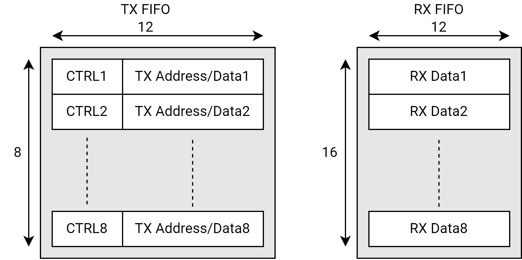
Each control word (CTRL) is 4 bit length:
- [TB]
- [ACKNACK]
- [STOP]
- [START]
Each entry in the Tx FIFO has a control word concatenated with Address/Data byte. The control word has control information to send/receive that particular byte. Note that Transmit FIFO has 8 entries and RX FIFO has 16 entries. Interrupt/DMA requests are made when the Tx FIFO is empty or when Rx FIFO is half full.
Programming model for Case 1
- Core initially programs the ICR for FIFO mode. It then receives a Tx FIFO empty interrupt if in PIO mode or a DMA request if in DMA mode.
- The core/DMA then writes 1 address byte + 7 data bytes (Byte1-Byte7) to the Tx FIFO (with each byte having a corresponding control word).
- I2C starts sending out the bytes and when the Tx FIFO is empty, it generates a Tx FIFO empty interrupt/DMA request.
- The core/DMA then writes the last 3 bytes (Byte8-Byte10) to the Tx FIFO.
- I2C sends out the last 3 bytes, and when it sees that STOP has been sent out, it sets the ISR[TX_DONE] bit and generates an interrupt.
- The core then cleans up the control and status registers (example: Clear ICR[STOP] bit, clear ISR[TX_DONE] bit) and starts the next transaction (set ICR[TX_BEGIN] bit).

Programming Model for Case 2
- Core initially programs the ICR for FIFO mode. It then receives a Tx FIFO empty interrupt if in PIO mode or a DMA request if in DMA mode.
- The core/DMA then writes 1 Addr + 7 Data Bytes to the TX FIFO (control word + dummy data since it is a Read transaction).
- After the address is sent out on the bus, for each control word, a Read byte is received and saved off in the Rx FIFO. Once the Tx FIFO is empty (note that there are 7 bytes in the Rx FIFO by now), an interrupt/DMA request is made and the remaining bytes (1 data byte from Read transaction and 3 bytes from the next Write transaction) are loaded into the Tx FIFO.
- After the 8 byte is received into the Rx FIFO, the Rx FIFO Half full interrupt/DMA request is set. This Read data now needs to be read out of the FIFO.
- By now, the Read transaction is also done. But since there is NO stop bit after the Read and instead Repeated Start is used for the Write Transaction, the ISR[TX_DONE] status bit is NOT set as it would have normally been set at the end of a transaction.
- I2C now starts the Write transaction by sending out the Address followed by the 2 Write bytes.
- Once the Write transaction is done, ICR[TX_BEGIN] is automatically cleared and ISR[TX_DONE] bit is set, which generates an interrupt to the core.

14.7.3.17 Slave Operations
How I2C unit operates as a slave device is tabled below.
| I2C Slave Action | Mode of Operation | Definition |
|---|---|---|
| Slave-receive (default mode) | Slave-receive only | - The I2C monitors all slave address transactions. - ICR[IUE] must be set. - The I2C monitors bus for Start conditions. When a Start is detected, the interface reads the first 8 bits and compares the most significant 7 bits with the 7-bit ISAR. If there is a match, the I2C sends an ACK. - If the eighth bit of the first byte (R/nW bit) is low, the I2C stays in Slave-Receive mode, and ISR[SAD] is cleared. If R/nW bit is high, the I2C unit switches to Slave-Transmit mode, and ISR[SAD] is set. |
| Set the slave address - detected bit | Slave-receive Slave-transmit | - Indicates the interface has detected an I2C operation that addresses current I2C. - An interrupt is generated, if enabled, after the matching slave address is received and acknowledged. |
| Read one byte of I2C data from the IDBR | Slave-receive only | - This operation occurs when ISR[IRF] is set and ICR[TB] is clear. If enabled, the IDBR receive-full interrupt is generated. - Eight bits are read from the serial bus into the shift register. When a full byte has been received and the ACK/NAK bit is completed, the byte is transferred from the Shift register to the IDBR. - Occurs when the IDBR receive full bit in the ISR is set and the transfer byte bit is clear. If enabled, the IDBR receive-full interrupt is signalled to the CPU. - Software reads one data byte from the IDBR. When the IDBR is read, the software must write the preferred ICR[ACKNAK] bit and sets ICR[TB]. This causes the I2C to stop inserting wait states and let the master transmitter transmit the next chunk of information. |
| Transmit Acknowledge to master transmitter | Slave-receive only | - As a slave receiver, the I2C pulls the SDA line low to generate the ACK pulse during the high SCL period. - ICR[ACKNAK] controls the acknowledge pulse that the I2C drives. See Section I2C Acknowledge |
| Write one byte of I2C data to the IDBR | Slave-transmit only | - This operation occurs when ISR[ITE] is set and ICR[TB] is clear. If enabled, the IDBR transmit-empty interrupt is generated. - The software must write a data byte to IDBR and sets ICR[TB] to start the transfer. |
| Wait for Acknowledge from master receiver | Slave-transmit only | - As a slave transmitter, the I2C releases the SDA line to allow the master receiver to pull the line low for the ACK. See Section I2C Acknowledge. |
14.7.3.18 Mode Programming Examples
Initialize Unit
- Set the slave address in the ISAR
- Enable preferred interrupts in the ICR
- If the I2C unit is a HS-mode slave, set ICR[MODE] = 0b10 or 0b11. Software should always set the HS mode bit (ICR[16]) as that bit makes the I2C HS capable. This bit does not affect the non-HS transfers.
- Set the ICR[IUE] bit to enable the I2C
Transmit n Bytes as a Slave
- When a slave-address-detected interrupt occurs. Read ISR register: ISR[SAD] = 1, ISR[UB] = 1, ISR[RWM] = 1, ISR[ACKNAK] = 0
- Write a 1 to the ISR[SAD] bit to clear the interrupt
- Return from interrupt
- Load data byte to transfer in the IDBR
- Set ICR[TB] bit
- When an IDBR transmit-empty interrupt occurs. Read ISR register: ISR[ITE] = 1, ISR[ACKNAK] = 0, ISR[RWM] = 0
- Load data byte to transfer in the IDBR
- Set the ICR[TB] bit
- Write a 1 to the ISR[ITE] bit to clear interrupt
- Return from interrupt
- Repeat steps 6 to 10 for n-1 times. If, at any time, the slave does not have data, the I2C keeps SCL low until data is available
- When a IDBR transmit-empty interrupt occurs
- Read ISR register: ISR[ITE] = 1, ISR[ACKNAK] = 1, ISR[RWM] = 0
- Write a 1 to the ISR[ITE] bit to clear interrupt
- Return from interrupt
- When a slave-Stop-detected interrupt occurs. Read ISR register: ISR[UB] = 0, ISR[SSD] = 1
- Write a 1 to the ISR[SSD] bit to clear interrupt
Receive n Bytes as a Slave
- When a slave-address-detected interrupt occurs. Read ISR register: ISR[SAD] = 1, ISR[UB] = 1, ISR[RWM] = 0
- Write a 1 to the ISR[SAD] bit to clear the interrupt
- Return from interrupt
- Set ICR[TB] bit to initiate the transfer
- When an IDBR receive-full interrupt occurs. Read ISR register: ISR[IRF] = 1, ISR[ACKNAK] = 0, ISR[RWM] = 0
- Read IDBR to get the received byte
- Write a 1 to the ISR[IRF] bit to clear interrupt
- Return from interrupt
- Repeat steps 5 to 8 for n-1 times. Once the IDBR is full, the I2C keeps SCL low until the data is read.
- Set ICR[TB] bit to release I2C bus and allow next transfer
- When a slave-stop-detected interrupt occurs. Read ISR register: ISR[UB] = 0, ISR[SSD] = 1. Write a 1 to the ISR[SSD] bit to clear interrupt
High-speed Mode: Transmit 1 Byte as a Slave
- Enable slave address detect interrupts. Set ICR[SADIE]
- Enable high speed mode
- Set ICR[MODE] = 0b10 or 0b11
- A master sends a master code at the standard-mode or fast-mode data rate. Then, a slave address is sent at the high speed mode data rate.
- Wait for the slave address detect interrupt
- Read the ISR: slave address detect (1), Unit Busy (1), R/nW bit (1), ACK/NAK (0)
- Write a 1 to the ISR[SAD] bit to clear the interrupt
- Load the IDBR with the data to be written (read by the master)
- Set the ICR[TB] bit
- When an IDBR transmit-empty interrupt occurs
- Read ISR: IDBR transmit empty (1), unit busy (1), ACKNAK (1), R/nW bit (0)
- Write a 1 to the ISR[ITE] bit to clear interrupt
- Return from interrupt
- Wait for a slave stop detect interrupt
- Read ISR: slave stop detect (1), Unit Busy (0)
- Write a 1 to the ISR[SSD] bit to clear interrupt
High-speed Mode: Receive 1 Byte as a Slave
- Enable slave address detect interrupts. Set ICR[SADIE]
- Enable high speed mode
- Set ICR[MODE] = 0b10 or 0b11
- A master sends a master code at the standard-mode or fast-mode data rate. Then a slave address is sent at the high speed mode data rate.
- Wait for the slave address detect interrupt
- Read the ISR: slave address detect (1), Unit Busy (1), R/nW bit (0), ACK/NAK (0)
- Write a 1 to the ISR[SAD] bit to clear the interrupt
- Set the ICR[TB] bit to initiate transfer
- When an IDBR receive-full interrupt occurs
- Read ISR: IDBR receive full (1), unit busy (1), ACKNAK (0), R/nW bit (0)
- Read IDBR to get the received byte
- Write a 1 to the ISR[IRF] bit to clear interrupt
- Return from interrupt
- Set ICR[TB] bit to release I2C bus and allow the next transfer
- Wait for a slave stop detect interrupt
- Read ISR: slave stop detect (1), Unit Busy (0)
- Write a 1 to the ISR[SSD] bit to clear interrupt
14.7.3.19 Glitch Suppression Logic
The I2C unit has built-in glitch-suppression logic. The glitch suppression logic is implemented differently depending on whether the I2C unit is in Fast/Standard (F/S) mode or High-speed (HS) mode.
For F/S mode, the glitch suppression specification is 50ns.
-
Glitches are suppressed for a length of time given by the formula:
- Suppression time = 4 * (1 / I2C input clock frequency)
-
For example, with a 31.5 MHz input clock frequency, glitches of 127 ns or shorter are suppressed.
For HS mode, the glitch suppression specification is 10 ns.
-
Glitches are suppressed for a length of time given by the formula:
- Suppression time = 1 * (1 / I2C input clock frequency)
-
For example, with a 61.44 MHz internal input clock frequency, glitches of 16.3 ns or shorter are suppressed.
14.7.3.20 Reset Conditions
When performing a reset on the I2C unit, the following conditions must be met to ensure proper operation:
-
Bus and Unit Status Checks:
- Ensure the I2C unit is not busy by verifying ISR[UB] = 0 before asserting a reset.
- After the reset, confirm that the I2C bus is idle by checking ISR[IBB] = 0 before enabling the unit.
-
Reset Behavior:
- When a reset is triggered, all registers return to their default reset values except for the ISAR register, which remains unchanged.
- Setting the ICR[UR] bit initiates a reset while preserving the I2C Memory-Mapped Registers (MMRs).
To reset the I2C unit using the ICR register, follow these steps:
- Set the reset bit in the ICR register and clear the remainder of the register
- Clear the ISR register
- Clear reset in the ICR
14.7.4 Register Descriptions
| Name | Address |
|---|---|
| I2C0_BASE | 0xD4010800 |
| I2C1_BASE | 0xD4011000 |
| I2C2_BASE | 0xD4012000 |
| I2C3_BASE (SEC_I2C) | 0xF0614000 |
| I2C4_BASE | 0xD4012800 |
| I2C5_BASE | 0xD4013800 |
| I2C6_BASE | 0xD4018800 |
| I2C8_BASE (PWR_I2C) | 0xD401D800 |
| R_I2C0_BASE | 0xC0886000 |
| R_I2C1_BASE | 0xC0886100 |
| R_I2C2_BASE (PWR_I2C) | 0xC0886200 |
ICR REGISTER
The bits in the I2C Control register (ICR) are used to control the I2C unit. These are read/write registers. Ignore reads from reserved bits.
Offset: 0x0
| Bits | Field | Type | Reset | Description |
|---|---|---|---|---|
| 31 | RXOV_IE | RW | 0x0 | Receive FIFO Overrun Interrupt Enable. 0 = Receive FIFO overrun (ISR[RXOV]) interrupt is not enabled. 1 = Receive FIFO overrun (ISR[RXOV]) interrupt is enabled. |
| 30 | RXF_IE | RW | 0x0 | Receive FIFO Full Interrupt Enable. 0 = Receive FIFO full (ISR[RXF]) interrupt is not enabled. 1 = Receive FIFO full (ISR[RXF]) interrupt is enabled. |
| 29 | RXHF_IE | RW | 0x0 | Receive FIFO Half Full Interrupt Enable. 0 = Receive FIFO half full (ISR[RXHF]) interrupt is not enabled. 1 = Receive FIFO half full (ISR[RXHF]) interrupt is enabled. |
| 28 | TXE_IE | RW | 0x0 | Transmit FIFO Empty Interrupt Enable. 0 = Transmit FIFO empty (ISR[TXE]) interrupt is not enabled. 1 = Transmit FIFO empty (ISR[TXE]) interrupt is enabled. |
| 27 | TXDONE_IE | RW | 0x0 | Transaction Done Interrupt Enable. 0 = Transaction done (ISR[TXD]) interrupt is not enabled. 1 = Transaction done (ISR[TXD]) interrupt is enabled. |
| 26 | MSDE | RW | 0x0 | Master Stop Detected Enable. 0 = Master Stop Detect (ISR[MSD]) status is not enabled. 1 = Master Stop Detect (ISR[MSD]) status is enabled. |
| 25 | MSDIE | RW | 0x0 | Master Stop Detected Interrupt Enable. 0 = Disable interrupt. 1 = Enables the I2C unit to interrupt upon detecting a Master Stop sent by the I2C unit. |
| 24 | SSDIE | RW | 0x0 | Slave Stop Detected Interrupt Enable. 0 = Disable interrupt. 1 = Enables the I2C to interrupt when it detects a Stop condition while in slave mode. |
| 23 | SADIE | RW | 0x0 | Slave Address Detected Interrupt Enable. 0 = Disable interrupt. 1 = Enables the I2C to interrupt upon detecting a slave address match or a general call address. |
| 22 | BEIE | RW | 0x0 | Bus Error Interrupt Enable. 0 = Disable interrupt. 1 = Enables the I2C to interrupt for the following I2C bus errors. |
| 21 | GCD | RW | 0x0 | General Call Disable. 0 = Enable the I2C to respond to general call messages. 1 = Disable I2C response to general call messages as a slave. This bit must be set when sending a master mode general call message from the I2C. |
| 20 | DRFIE | RW | 0x0 | DBR Receive Full Interrupt Enable. 0 = Disable interrupt. 1 = Enables the I2C to interrupt when the IDBR has received a data byte from the I2C bus. |
| 19 | ITEIE | RW | 0x0 | IDBR Transmit Empty Interrupt Enable. 0 = Disable interrupt. 1 = Enables the I2C to interrupt after transmitting a byte onto the I2C bus. |
| 18 | ALDIE | RW | 0x0 | Arbitration Loss Detected Interrupt Enable. 0 = Disable interrupt. 1 = Enables the I2C to interrupt upon losing arbitration while in master mode. |
| 17 | CURSRC_FIX_BYPASS | RW | 0x0 | Bypass the cursrc fix. 0 = cursrc fix effective. 1 = Bypass the cursrc fix. |
| 16 | HS_STRETCH_FIX_BYPASS | RW | 0x0 | Bypass the hs stretch fix. 0 = hs stretch fix effective. 1 = Bypass the hs stretch fix. |
| 15 | RSVD | RO | 0x0 | Reserved for future use. |
| 14 | IUE | RW | 0x0 | I2C Unit Enable. 0 = Disables the unit and does not master any transactions or respond to any slave transactions. 1 = Enables the I2C (defaults to slave-receive mode). Software must ensure the I2C bus is idle before setting this bit. Software must ensure that the internal clock to the I2C unit is enabled before setting or clearing this bit. |
| 13 | SCLE | RW | 0x0 | SCL Enable. 0 = Disables the I2C from driving the SCL line. 1 = Enables the I2C clock output for master-mode operation. |
| 12 | MA | RW | 0x0 | Master Abort. Used by the I2C in master mode to generate a Stop without transmitting another data byte. 0 = The I2C transmits Stop if ICR[STOP] is set. 1 = The I2C sends Stop without data transmission. In Master-Transmit Mode: - After transmitting a data byte: 1. The ICR[TB] bit is cleared. 2. The IDBR[ITE] bit is set. - When no more data needs to be sent: 1. Set the Master Abort (MA) bit to send a Stop condition. 2. Ensure the ICR[TB] bit remains clear during this operation. In Master-Receive Mode: - If a NAK is sent without a Stop (because ICR[STOP] was not set) and the unit does not send a repeated Start: 1. Setting the MA bit forces a Stop. 2. Again, the ICR[TB] bit must remain clear. |
| 11 | I2C_BUS_RESET_REQ | RW | 0x0 | The I2C will do bus reset upon this bit set. This bit is self-cleared. |
| 10 | UR | RW | 0x0 | Unit Reset. 0 = No reset. 1 = Reset the I2C only. |
| 9:8 | MODE | RW | 0x2 | Bus Mode (Master operation): 2'h0 : Standard-mode: Supports up to 100 Kbps 2'h1 : Fast-mode: Supports up to 400 Kbps 2'h2 : High-speed (HS) mode: Supports up to 3.3 Mbps in master mode and 3.4 Mbps in slave mode; operates in Standard mode when not performing a high-speed transfer 2'h3 : High-speed (HS) mode: Supports up to 3.3 Mbps in master mode and 3.4 Mbps in slave mode; operates in Fast mode when not performing a high-speed transfer Bus Mode (Slave operation): 2'h0, 2'h1 : HS-mode Disabled: I2C unit uses Standard/Fast mode timing on the SDA pin 2'h2, 2'h3 : HS-mode Enabled: I2C unit uses HS-mode timing on the SDA pin when a master code is received |
| 7 | DMA_EN | RW | 0x0 | DMA Enable for both TX and RX FIFOs. 0 = DMA mode is NOT enabled. 1 = DMA mode enabled. |
| 6 | GPIOEN | RW | 0x0 | GPIO mode Enable for SCL during HS mode. 0 = GPIO mode disabled: SCL operates as an open-collector output. 1 = GPIO mode enabled: SCL is directly driven by the I2C unit. |
| 5 | FIFOEN | RW | 0x0 | FIFO mode. 0 = FIFO mode disabled; Data is read from or written to the IDBR directly. 1 = FIFO mode enabled; Data is managed through the Transmit and Receive FIFOs. |
| 4 | TXBEGIN | RW | 0x0 | Transaction Begin. Set this for a new Transaction only after ISR[TXDONE] is set. 0 = No transaction starting. 1 = A new transaction begins. This is cleared by the hardware at the end of each transaction after a STOP bit is sent out. The software has to set it again to start a new transaction. |
| 3 | TB | RW | 0x0 | Transfer Byte. Used to send or receive a byte on the I2C bus. 0 = Cleared by I2C when the byte is sent/received. 1 = Send/receive a byte. Monitoring this bit can determine when the byte transfer has completed. In master or slave mode, after each byte transfer including acknowledge pulse, the I2C holds the SCL line low (inserting wait states) until TB is set. |
| 2 | ACKNAK | RW | 0x0 | The positive/negative acknowledge control bit, ACK/NAK, defines the type of acknowledge pulse sent by the I2C when in master receive mode. 0 = Send a positive acknowledge (ACK) pulse after receiving a data byte. 1 = Send a negative acknowledge (NAK) pulse after receiving a data byte. The I2C automatically sends an ACK pulse when responding to its slave address or when responding in slave-receive mode, regardless of the ACKNAK control-bit setting. |
| 1 | STOP | RW | 0x0 | Stop. Used to initiate a Stop condition after transferring the next data byte on the I2C bus when in master mode. In master-receive mode, the ACKNAK control bit must be set in conjunction with the STOP bit. 0 = Do not send a Stop. 1 = Send a Stop. |
| 0 | START | RW | 0x0 | Start. Used to initiate a Start condition to the I2C unit when in master mode. 0 = Do not send a Start pulse. 1 = Send a Start pulse. |
ISR REGISTER
I2C interrupts are signaled to the interrupt controller by the I2C Interrupt Status register. Software uses the ISR bits to check the status of the I2C unit and bus. ISR bits (bits 9-5) are updated after the ACK/NAK bit has completed on the I2C bus.
The I2C has transmitted a STOP signal when configured as a master when :
- IDBR receive full
- IDBR transmit empty
- Slave address detected
- Bus error detected
- Stop condition detect
- Arbitration lost
Offset: 0x4
| Bits | Field | Type | Reset | Description |
|---|---|---|---|---|
| 31 | RXOV | RW1C | 0x0 | Receive FIFO Overrun (Used in FIFO mode). 0 = Transmit FIFO NOT overrun. 1 = Transmit FIFO overrun happened. |
| 30 | RXF | RW1C | 0x0 | Receive FIFO Full (Used in FIFO mode). 0 = Receive FIFO is NOT full. 1 = Receive FIFO is full. |
| 29 | RXHF | RW1C | 0x0 | Receive FIFO Half Full (Used in FIFO mode). 0 = Receive FIFO is NOT half full. 1 = Receive FIFO is half full. |
| 28 | TXE | RW1C | 0x0 | Transmit FIFO Empty (Used in FIFO mode). 0 = Transmit FIFO is NOT empty. 1 = Transmit FIFO is empty. |
| 27 | TXDONE | RW1C | 0x0 | Transaction Done (Used in FIFO mode). 0 = Transaction is NOT done. 1 = Transaction is done. |
| 26 | MSD | RW1C | 0x0 | Master Stop Detected. 0 = No Master Stop Detected. 1 = Set when the I2C detects a Stop while in master-receive or master-transmit mode. |
| 25 | RSVD | RO | 0x0 | Reserved for future use. |
| 24 | SSD | RW1C | 0x0 | Slave Stop Detected. 0 = No Stop detected. 1 = Set when the I2C detects a Stop while in slave-receive or slave-transmit mode. |
| 23 | SAD | RW1C | 0x0 | Slave Address Detected. 0 = No slave address was detected. 1 = The I2C detected a seven-bit address that matches the general call address or ISAR. An interrupt is signaled when enabled in the ICR. |
| 22 | BED | RW1C | 0x0 | Bus Error Detected. 0 = No error detected. 1 = The I2C sets this bit when it detects one of the following error conditions: - As a master transmitter, no ACK is detected on the interface after a byte is sent. - As a slave receiver, the I2C generates a NAK pulse. |
| 21 | GCAD | RW1C | 0x0 | General Call Address Detected. 0 = No general call address received. 1 = I2C received a general call address. |
| 20 | IRF | RW1C | 0x0 | IDBR Receive Full. 0 = The IDBR has not received a new data byte or the I2C is idle. 1 = The IDBR register received a new data byte from the I2C bus. An interrupt is signaled when enabled in the ICR. |
| 19 | ITE | RW1C | 0x0 | IDBR Transmit Empty. 0 = The data byte is still being transmitted. 1 = The I2C has finished transmitting a data byte on the I2C bus. An interrupt is signaled when enabled in the ICR. |
| 18 | ALD | RW1C | 0x0 | Arbitration Loss Detected. Used during multi-master operation. 0 = Cleared when arbitration is won or never took place. 1 = Set when the I2C loses arbitration. |
| 17 | EBB | RO | 0x0 | Early Bus Busy. 0 = Bus is idle or the I2C unit is actively using the bus (unit busy). 1 = Early Bus Busy: SCL or SDA is low without detecting a START condition. Bit will remain set until the I2C unit detects the bus is idle by detecting a STOP condition. Bit will also be set whenever the IBB bit is set. |
| 16 | IBB | RO | 0x0 | I2C Bus Busy. 0 = I2C bus is idle or the I2C unit is actively using the bus (unit busy). 1 = Bus is busy due to external activity (another master using the bus). |
| 15 | UB | RO | 0x0 | Unit Busy. 0 = I2C not busy. 1 = I2C is busy. This is defined as the time between the first Start and Stop. |
| 14 | ACKNAK | RO | 0x0 | ACK/NACK Status. 0 = The I2C received or sent an ACK on the bus. 1 = The I2C received or sent a NAK. On the bus, this bit is used in slave-transmit mode to determine when the byte transferred is the last one. This bit is updated after each byte and ACK/NAK information is received. |
| 13 | RWM | RO | 0x0 | Read/Write Mode. 0 = The I2C is in master-transmit or slave-receive mode. 1 = The I2C is in master-receive or slave-transmit mode. This is the R/nW bit of the slave address. It is cleared automatically by hardware after a Stop state. |
| 12:0 | RSVD | RO | 0x0 | Reserved for future use. |
ISAR REGISTER
- The ISAR defines the I2C' s seven-bit slave address.
- In slave-receive mode, the device responds only when the seven-bit address matches the value stored in the ISAR.
- The system writes to the ISAR before enabling I2C operations.
- The ISAR is fully programmable (no address is assigned to the I2C) so it can be set to a value other than those of hard-wired I2C slave peripherals in the system.
These are read/write registers. Ignore reads from reserved bits.
Offset: 0x8
| Bits | Field | Type | Reset | Description |
|---|---|---|---|---|
| 31:7 | RSVD | RO | 0x0 | Reserved for future use. |
| 6:0 | SLAVE_ADDRESS | RW | 0x0 | The seven-bit address to which the I2C responds when in slave-receive mode. |
IDBR REGISTER
The I2C Data Buffer Register (IDBR) is used to transmit and receive data from the I2C bus. It is accessed by programmed I/O on one side and the I2C Shift register on the other side.
-
Receiving Data:
- The IDBR receives data coming into the I2C unit after a full byte is received and acknowledged.
-
Transmitting Data:
- The core writes data going out of the I2C to the IDBR, which then sends it to the serial bus.
IDBR Operation in Transmit Mode (Master or Slave)
-
Data Writing to IDBR:
- When the I2C is in transmit mode (master or slave), the core writes data to the IDBR over the internal bus.
- Data is written to the IDBR either when a master transaction is initiated or when the IDBR transmit-empty interrupt is signaled.
-
Data Transfer from IDBR to Shift Register:
- Data moves from the IDBR to the Shift register when the transfer byte bit is set.
-
Transmit-Empty Interrupt:
- The IDBR transmit-empty interrupt (if enabled) is signaled when a byte is transferred on the I2C bus and the acknowledge cycle is complete.
-
Wait States:
- If the IDBR is not written by the core and a Stop condition is not in place before the I2C bus is ready to transfer the next byte packet, the I2C unit inserts wait states until the core writes the IDBR and sets the transfer byte bit.
IDBR Operation in Receive Mode (Master or Slave)
-
Data Reading from IDBR:
- When the I2C is in receive mode (master or slave), the core reads data from the IDBR over the internal bus.
-
Receive-Full Interrupt:
- The core reads data from the IDBR when the IDBR receive-full interrupt is signaled.
-
Data Movement from Shift Register to IDBR:
- Data moves from the Shift register to the IDBR when the acknowledge cycle is complete.
-
Wait States:
- The I2C unit inserts wait states until the IDBR is read.
-
Acknowledge Pulse:
- For more information on the acknowledge pulse in receive mode, See Section I2C Acknowledge.
-
Next Byte Transfer:
- After the software reads the IDBR, the ICR[ACKNAK] register is written by the software to allow the next byte transfer to proceed on the I2C bus.
These are read/write registers. Ignore reads from reserved bits.
| Bits | Field | Type | Reset | Description |
|---|---|---|---|---|
| 31:8 | RSVD | RO | 0x0 | Reserved for future use. |
| 7:0 | DATA_BUFFER | RW | 0x0 | Buffer for I2C bus send/receive data. |
ILCR REGISTER
The I2C must generate the SCL in master mode and the Load Count Monitor register (ILCR) allows minor adjustments to this clock.
The reset value of this register are determined based on a 31.5 MHz I2C input clock which allows the maximum frequency to be derived for
- Fast mode (up to 400 Kbps)
- Normal mode (up to 100 Kbps)
Due to input clock frequency limitations, the default values of ILCR only generate an SCL than can support up to 1.8 Mbps for HS mode.
For alternate clock setting, an alternate 61.44 MHz I2C input clock is selected (via writing CCU ACCR1[8] to 1 while the I2C is disabled), the recommended value of ILCR to achieve the proper Fast, Normal and High-Speed SCL frequencies is
- 32'5 h 082CBB56
This register must also be written while the I2C is disabled.
The SCL Frequency adjustment:
- Increasing the load value decreases the SCL frequency.
- Decreasing the load value increases the SCL frequency.
- Each increment or decrement corresponds to one I2C clock period.
Reset values are designed to allow the highest possible SCL frequency while meeting the I2C Bus Specification Version 2.1 minimum requirements. This register should be written before enabling the I2C and should not be modified during bus activity.
Writing all zeros to any of the four individual Load Values prevents the I2C from generating an SCL for that specific mode when operating as a master.
Extreme caution is required when modifying this register to avoid disrupting I2C operations.
Offset: 0x10
| Bits | Field | Type | Reset | Description |
|---|---|---|---|---|
| 31:27 | HLVL | RW | 0x1 | Load value for High-Speed Mode SCL (master mode) — Low phase. With the reset value, the I2C in master mode generates an SCL supporting data rates up to 1.8 Mbps. |
| 26:18 | HLVH | RW | 0xB | Load value for High-Speed Mode SCL (master mode) — High phase. With the reset value, the I2C in master mode generates an SCL supporting data rates up to 1.8 Mbps. |
| 17:9 | FLV | RW | 0x5D | Load value for Fast Mode SCL (master mode) — Both high and low phases. With the reset value, the I2C in master mode generates an SCL supporting data rates up to 400 Kbps. |
| 8:0 | SLV | RW | 0x156 | Load value for Standard Mode SCL (master mode) — Both high and low phases. With the reset value, the I2C in master mode generates an SCL supporting data rates up to 100 Kbps. |
IWCR REGISTER
The I2C Wait Count register controls the setup and hold times during slave mode (standard, fast, or high speed).
This register works together with the ILCR register control the setup and hold times for all modes.
Offset: 0x14
| Bits | Field | Type | Reset | Description |
|---|---|---|---|---|
| 31:15 | RSVD | RO | 0x0 | Reserved for future use. |
| 14:10 | HS_COUNT2 | RW | 0x5 | Count value for defining high speed mode STOP bit setup and hold times. Default: Decimal 5 |
| 9:5 | HS_COUNT1 | RW | 0x1 | Count value for defining high speed mode START bit setup and hold times. Default: Decimal 1 |
| 4:0 | COUNT | RW | 0x1A | Controls the counter values defining the setup and hold times in standard and fast mode. Recommended values: 01010 = 33 MHz I2C functional clock 10100 = 66 MHz I2C functional clock Default: Decimal 26. |
IRCR REGISTER
The I2C bus reset cycle counter defines the cycles of SCL during bus reset
Offset: 0x18
| Bits | Field | Type | Reset | Description |
|---|---|---|---|---|
| 31:8 | RSVD | RO | 0x0 | Reserved for future use. |
| 7 | I2C_SDA_GLITCH_FIX_BYPASS | RW | 0x0 | Bypass the SDA glitch fix. 0 = The SDA glitch fix effective. 1 = Bypass the SDA glitch fix. |
| 6 | I2C_READ_HANG_FIX_BYPASS | RW | 0x0 | Bypass the read hang fix. 0 = The read hang fix effective. 1 = Bypass the read hang fix. |
| 5 | SCL_SW_CTRL | RW | 0x0 | 1 = The SCL output is controlled by SW_SCL. |
| 4 | SW_SCL | RW | 0x0 | 0 = SCL output set to 0. 1 = SCL output set to 1. |
| 3:0 | RST_CYC | RW | 0x9 | The cycles of SCL during bus reset. |
IBMR REGISTER
The I2C Bus Monitor register (IBMR) tracks the status of the SCL and SDA pins. The values of these pins are recorded in this read-only IBMR, so software can determine when the I2C bus is hung and the I2C unit must be reset.
This a read-only register. Ignore reads from reserved bits.
Offset: 0x1C
| Bits | Field | Type | Reset | Description |
|---|---|---|---|---|
| 31:2 | RSVD | RO | 0x0 | Reserved for future use. |
| 1 | SCL | RO | 0x1 | IBMR[SCL] continuously reflects the value of the SCL pin. |
| 0 | SDA | RO | 0x1 | IBMR[SDA] continuously reflects the value of the SDA pin. |
WFIFO REGISTER
The I2C Write FIFO has 8 entries and each entry is 12-bit wide (4-bit control + 8-bit data).
This FIFO can be filled up in PIO or DMA mode.
If this FIFO is empty, an interrupt or a DMA request is generated.
Offset: 0x20
| Bits | Field | Type | Reset | Description |
|---|---|---|---|---|
| 31:12 | RSVD | RO | 0x0 | Reserved for future use. |
| 11:8 | CONTROL | RO | 0x0 | I2C Bus send/receive data control bits. These control bits are essential for ICR[3:0] bits. |
| 7:0 | DATA | RO | 0x0 | I2C Bus send data for Write Transactions and dummy data for Read Transactions. |
WFIFO_WPTR REGISTER
The I2C Write FIFO Pointer has the TX FIFO write entry location information.
This is a read/write register.
Software can write '0' to this register to flush the FIFO after handling interrupts like Bus error, Arbitration loss, etc.
Offset: 0x24
| Bits | Field | Type | Reset | Description |
|---|---|---|---|---|
| 31:4 | RSVD | RO | 0x0 | Reserved for future use. |
| 3:0 | DATA | RW | 0x0 | This is the location in the TX FIFO where the next entry will be written to by the software. |
WFIFO_RPTR REGISTER
The I2C Write FIFO Read Pointer has the TX FIFO read entry location information.
This is a read/write register.
Software can write '0' to this register to flush the FIFO after an interrupt.
Offset: 0x28
| Bits | Field | Type | Reset | Description |
|---|---|---|---|---|
| 31:4 | RSVD | RO | 0x0 | Reserved for future use. |
| 3:0 | DATA | RW | 0x0 | This is the location in the TX FIFO where the next entry will be read from by the hardware. |
RFIFO REGISTER
The I2C Read FIFO has 16 entries and each entry is 8-bit wide (8-bit data).
This FIFO can be emptied in PIO or DMA mode.
If this FIFO is half full, an interrupt or a DMA request is generated.
Offset: 0x2C
| Bits | Field | Type | Reset | Description |
|---|---|---|---|---|
| 31:12 | RSVD | RO | 0x0 | Reserved for future use. |
| 11:8 | CONTROL | RO | 0x0 | I2C Bus send/receive data control bits. These control bits are essential for ICR[3:0] bits. |
| 7:0 | DATA | RO | 0x0 | I2C Bus send data for Write Transactions and dummy data for Read Transactions. |
RFIFO_WPTR REGISTER
The I2C Read FIFO Write Pointer has the RX FIFO write entry location information.
This is a read/write register.
Software can write '0' to this register to flush the FIFO after handling interrupts like Bus error, Arbitration loss, etc.
Offset: 0x30
| Bits | Field | Type | Reset | Description |
|---|---|---|---|---|
| 31:4 | RSVD | RO | 0x0 | Reserved for future use. |
| 3:0 | DATA | RW | 0x0 | This is the location in the TX FIFO where the next entry will be written to by the software. |
RFIFO_RPTR REGISTER
The I2C Read FIFO Read Pointer has the RX FIFO read entry location information.
This is a read/write register.
Software can write '0' to this register to flush the FIFO after an interrupt.
Offset: 0x34
| Bits | Field | Type | Reset | Description |
|---|---|---|---|---|
| 31:4 | RSVD | RO | 0x0 | Reserved for future use. |
| 3:0 | DATA | RW | 0x0 | This is the location in the RX FIFO where the next entry will be read from by the hardware. |